


Chapter 6 - Optional Equipment Installation
72
Adept Cobra s800 Inverted Robot User’s Guide, Rev C
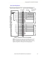
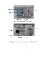
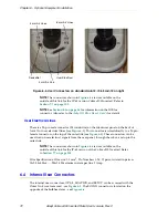
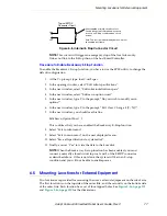
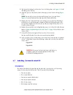
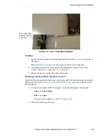
Figure 6-4. User Connectors on standard Joint 2. IP-65 Joint 2 on right.
NOTE:
are not available on the
outside of this link for the IP-65 version Cobra s800 Inverted. Refer to
NOTE:
for information on the IO Blox
connector. Also refer to the
for details.
User Electrical Lines
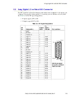
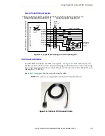
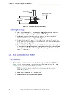
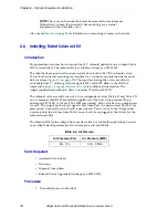
There is a 25-pin male connector (24 conductor) on the robot user panel on the back of
Joint 1 for user electrical lines (see
). This connector is wired directly to a 25-pin
female connector on the top of the outer link (see
). These connectors can be
used to run user electrical signals from the user panel, through the robot, and up to the
outer link.
NOTE:
are not available on the
outside of this link for the IP-65 version of the Cobra s800 Inverted. Refer
to
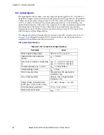
Wire Specifications: Wire size: 0.1 mm
2
, Pin Numbers 1-24, 12 pairs, twisted in pairs as
1&2, 3&4, 5&6, .... 23&24. Maximum current per line: 1 Amp.
6.4
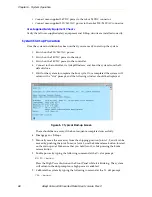
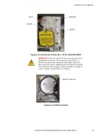
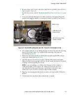
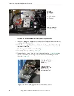
Internal User Connectors
The internal user connectors, OP3/4, EOAPWR, and ESTOP, can be accessed with the
Outer Link cover removed - see
. The SOLND connector is located on the
opposite of the bulkhead area - see
.
DeviceNet
4 mm Air Lines
6 mm Air Lines
User Electrical
4 mm Air Line