


Page 29 of 39
Fleet One Terminal Installation Manual
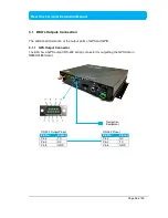
3.1.2 GPIO Output Port
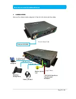
The BDU has a dedicated 10-pin phoenix connector to provide GPIO (General Purpose
Input/Output) interface to the external devices.
GPIO Port Pinout
GPIO Port Pin
Signal Name
Description of Signal
GPIO - 1
6V
To supply 6V DC source.
GPIO - 2
TX_OFF
To disable the antenna unit’s transmitter.
GPIO - 3
PDP_ON/OFF
To enable/disable the data connection.
GPIO - 4
BUZZER
To enable external ringer / buzzer for incoming call.
GPIO - 5
GND
To provide grounding for the whole system.
GPIO - 6
REMOTE_ON/OFF_SW
For the connection to Remote ON/ OFF switch away
from the BDU.
GPIO - 7
REMOTE_ON/OFF_LED
Power Indicator.
GPIO - 8
Reserve
Not in use,.
GPIO – 9
Reserve
Not in use,.
GPIO – 10
GND
To provide grounding for the whole system.
All wires for the GPIO connector shall use AWG 24 unscreened wire type.
I/O Connector Pinout


