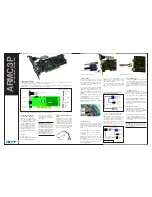
PA 7400
Table of contents
IV
Figures
Fig. 3-1: Wrong handling.................................................................................................... 4
Fig. 3-2: Correct handling .................................................................................................. 4
Fig. 5-1: Component scheme of the PA 7400 ................................................................... 9
Fig. 5-2: Jumper location and settings at delivery............................................................ 10
Fig. 5-3: selection of the interrupt lines through jumper J31 ............................................. 12
Fig. 5-4: Common interrupt: Example with IRQ3 .............................................................. 12
Fig. 5-5: Block of DIP switches DIP2 ................................................................................... 19
Fig. 5-6: Block of DIP switches DIP1 ................................................................................... 19
Fig. 6-1: Types of slots....................................................................................................... 21
Fig. 6-2: Opening the protective blister pack ................................................................... 21
Fig. 6-3: Inserting the board ............................................................................................. 22
Fig. 6-4: Securing the board at the back cover ............................................................... 22
Fig. 6-5: ADDIREG registration program............................................................................ 24
Fig. 6-6: Configuring a new board ................................................................................... 26
Fig. 7-1: 25-pin SUB-D male connector for the serial port 1 .............................................. 29
Fig. 7-2: 9-pin SUB-D male connector for the serial port 2 ................................................ 30
Fig. 7-3: 26-pin male connector for the parallel port ....................................................... 30
Fig. 8-1: Bloc diagram of the board PA 7400................................................................... 31
Fig. 8-2: Operation without modem control signals ......................................................... 34
Fig. 8-3: Operation with modem control signals .............................................................. 35
Fig. 8-4: Enabling the RS 422 transmitter .......................................................................... 36
Fig. 8-5: Inserting a terminator and inverting the open-circuit potential........................... 37
Fig. 8-6: RS 422 cabling for serial port 1 ........................................................................... 37
Fig. 8-7: RS 422 cabling for serial port 2 ........................................................................... 38
Fig. 8-8: Enabling the automatic transmitter with the signals DTRA(B), RTSA(B) or DATA-DIR-1(2)
through jumper J11(6)............................................................................................... 38
Fig. 8-9: Enabling the receiver with jumper J16(7)............................................................ 39
Fig. 8-10: Inserting a terminator and inverting the open-circuit potential......................... 40
Fig. 8-11: RS 485 cabling for serial port 1 ......................................................................... 40
Fig. 8-12: RS 485 cabling for serial port 2 ......................................................................... 41
Fig. 8-13: Active transmission / active reception .............................................................. 42
Fig. 8-14: Active transmission / passive reception ............................................................ 43
Fig. 8-15: Passive transmission / active reception............................................................. 44
Fig. 8-16: Passive transmission/ passive reception............................................................ 44
Fig. 8-17: Selecting the reference point of the protection circuitry (serial port 1).............. 45
Fig. 8-18: Jumper settings - J9.......................................................................................... 46


