ADDAC SYSTEM
page 5
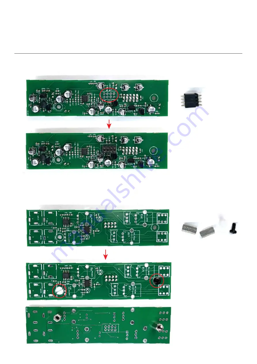
STEP 8:
Place and solder the 2x4 pinheader.
STEP 9:
Attach the spacers to the front pcb as shown below, notice the white plastic screw location.
ADDAC712 Assembly Guide
Page 1: ......
Page 2: ...February 2023 ADDAC712 Assembly Guide ADDAC SYSTEM page 2...
Page 3: ...a cutting pliers STEP 2 Proceed by locating the six 22uf capacitors notice the orientation printed on the pcb Tip soldering these caps is easy just place a dab of solder on the pad on your right left...
Page 4: ...citors orientation place their legs through the pcb holes and solder them to the pcb ADDAC SYSTEM page 4 STEP 7 Place and solder the 2x5 boxed pinheader Notice the indent orientation STEP 6 Place and...
Page 5: ...ADDAC SYSTEM page 5 STEP 8 Place and solder the 2x4 pinheader STEP 9 Attach the spacers to the front pcb as shown below notice the white plastic screw location ADDAC712 Assembly Guide...
Page 6: ...ADDAC SYSTEM page 6 STEP 10 Align both pcbs toghether and solder the pinheader to the top pcb STEP 11 Next locate the jacks and cut the thinest leg like shown below ADDAC712 Assembly Guide...
Page 7: ...pcb keeping it parallel to the front panel and proceed to solder all parts STEP 12 Place the remaining parts on the pcb allign the front panel and tighten the jacks and pots nuts Threaded Jacks Non t...
Page 8: ...ADDAC SYSTEM page 7 Finish it by placing the knobs and you ve finished the assembly process You re all done Happy patching ADDAC712 Assembly Guide...
Page 9: ...For feedback comments or problems please contact us at addac addacsystem com ADDAC712 ASSEMBLY GUIDE February 2023 Revision 01...
Page 10: ...ADDAC SYSTEM page 8 STEP 14 Next attach the bottom pcb and tighten the two bottom screws ADDAC712 Assembly Guide...