ADDAC SYSTEM
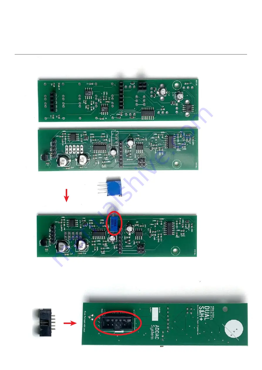
STEP 4:
Next carefully break the 2 pcbs apart, locate and solder the trimmer like shown below.
STEP 5:
Next locate and solder the 2x5 boxed pinheader like shown below.
page 5
ADDAC215 Assembly Guide
Page 1: ......
Page 2: ...March 2020 ADDAC215 Assembly Guide ADDAC SYSTEM page 2 ...
Page 3: ... preference We provide 2 options Short and Long range Short for 1v oct signals like a short portamento Long for smoothing cv voltages Each channel can be set diferently Other values can also be used ADDAC215 Assembly Guide SLEW TIME OPTIONS CHANNEL 2 CHANNEL 1 ...
Page 4: ...oldering these caps is easy just place a dab of solder on the pad on your right left pad if you re left handed and then with the help of a tweezer put the capacitor in place and reflow the previously tinned pad to reflow the solder while pushing the capacitor down Then solder the other pad STEP 2 Proceed by locating the 78L05 Regulator and solder it in place notice the orientation printed on the p...
Page 5: ...ADDAC SYSTEM page 4 STEP 3 Next proceed to locate the male and female pinheaders and solder them like shown below ADDAC215 Assembly Guide ...
Page 6: ...DAC SYSTEM STEP 4 Next carefully break the 2 pcbs apart locate and solder the trimmer like shown below STEP 5 Next locate and solder the 2x5 boxed pinheader like shown below page 5 ADDAC215 Assembly Guide ...
Page 7: ...ADDAC SYSTEM STEP 6 Next attach the spacer like shown below and proceed to place all front panel parts page 6 ADDAC215 Assembly Guide ...
Page 8: ...ADDAC SYSTEM page 7 STEP 7 After all parts are in place fit the frontpanel in and tighten all the nuts Proceed by soldering all pads in the back ADDAC215 Assembly Guide ...
Page 9: ...ADDAC SYSTEM page 8 STEP 8 Solder all the front parts pads ADDAC215 Assembly Guide ...
Page 10: ...ADDAC SYSTEM page 9 STEP 9 For the last step place the bottom screw ADDAC215 Assembly Guide ...
Page 11: ...ADDAC SYSTEM page 10 Place and tighten all remaining nuts and you re done Happy Patching ADDAC215 Assembly Guide ...
Page 12: ...it about 30 seconds for it to stabilize 2 Patch the NOISE Output to an oscilloscope 3 Adjust the trimmer until the level peaks at about 5 volts The 5 volt calibration is just a reference the user can calibrate it to any other range according to his wish ADDAC215 Assembly Guide Calibration INTERNAL NOISE LEVEL ...
Page 13: ...For feedback comments or problems please contact us at addac addacsystem com ADDAC215 ASSEMBLY GUIDE March 2020 Revision 01 ...