background image


3-7 

12704A Resistivity Chamber Operation Manual

3.3  Measurement


3.3 Measurement 

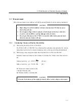
Perform measurement in accordance with the Operation Manual of each measuring instrument. 


1.


High voltage is used in insulation resistance measurement. Perform measure-
ment with great care. 

2.


Do not apply voltage without a sample or electrode protection sheet, otherwise 
excessive current will flow, causing damage to the electrodes. 

3.


Do not give vibrations to the 12704A or connected cables during measurement, 
otherwise measured values will vary. 


3.3.1 

Calculating Volume and Surface Resistivities 

(1)


When using the 8340A, 8252 or 5450/5451 

The 8340A, 8252 or 5450/5451 has a function that calculates automatically the volume 
and surface resistivities. For more information, refer to the respective Operation Manual. 

(2)


When using a measuring instrument other than the 8340A, 8252 and 5450/5451 

Substitute measured values for the formulas to calculate the volume and surface resistivi-
ties. 

Volume resistivity: 

t

Rv

63

.

19

v


[



cm] 

Surface resistivity: 

Rs

84

.

18

s


[

Rv: Measured volume resistance [

t: Sample thickness [cm] 
Rs: Measured surface resistance [


Measure the thickness of the sample previously with a vernier caliper or micrometer. 


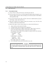
CAUTION


CAUTION

Summary of Contents for 12704A

Page 1: ... 2009 ADC CORPORATION First printing March 31 2009 All rights reserved Printed in Japan 12704A Resistivity Chamber OPERATION MANUAL Manual Number FOE 00000046B00 ...

Page 2: ......

Page 3: ... 1 1 Connecting with the 8340A 3 3 3 1 2 Connecting with the 8240 3 4 3 1 3 Connecting with the 8252 3 4 3 1 4 Connecting with the 5450 5451 3 5 3 2 Setting the Electrodes and a Sample 3 6 3 3 Measurement 3 7 3 3 1 Calculating Volume and Surface Resistivities 3 7 3 3 2 General Instructions 3 8 4 Specifications 4 1 Appendix A 1 A 1 How to Calculate Volume and Surface Resistivities A 2 A 2 Internal ...

Page 4: ......

Page 5: ...1 1 12704A Resistivity Chamber Operation Manual 1 Introduction Chapter 1 Introduction ...

Page 6: ...micro current meter or other measuring instruments Features The electrodes comply with JIS K6911 All the electrodes adopt conductive rubber for higher sample adhesion Easy sample attachment and detachment Volume and surface resistivity measurements can be switched by pressing the button switch The following functions are included for easy measurement 1 Voltage application to the electrodes stops w...

Page 7: ...ed Accessory List Name Model Quantity Remarks Electrode protection sheet MPX F0955A 1 For protection when not in use Operation Manual E12704A 1 Note Quote the model name of the accessory when ordering 2 Optional Accessory The 12704A optional accessories are listed below Specify the part number when ordering Table 1 2 Optional Accessory List Name Model Quantity Remarks Replacement rubber elec trode...

Page 8: ...n a cardboard box and store it in a low humidity area away from direct sun light When transporting the 12704A insert the electrode protection sheet and pack with the packaging materials used at delivery If the packaging materials have been lost pack the 12704A by using the following procedure a Wrap the 12704A with a plastic sheet b Put it in a cardboard box with thickness of 5 mm or more and prot...

Page 9: ...2 1 12704A Resistivity Chamber Operation Manual 2 Part Descriptions Chapter 2 Part Descriptions ...

Page 10: ...STIVITY switch the LO is always connected to the chassis The HI connection is disconnected when the cover is opened and is connected to the guard elec trode or opposed electrode when it is closed If a cable is disconnected with voltage being applied from a voltage source voltage generation will occur on the end of the cable Be sure to set the voltage OFF or STANDBY before disconnecting the cable 3...

Page 11: ... measurement to be come a high voltage application electrode Voltage is applied between the main electrode and this electrode 7 Opposed electrode feed terminal Inserting the opposed electrode to this terminal will apply voltage to the opposed electrode Insert the opposed electrode as pressing it down onto the ring electrode 8 RESISTIVITY switch A button switch to switch volume resistivity measurem...

Page 12: ...nical durability of 250 000 times operation However after it reaches the end of its service life it will be always OFF regardless of opening and closing of the cover 11 Lock Be sure to close and lock the cover before starting measurement If measurement is per formed without locking it a sample does not stick fast to the electrodes and correct meas ured values cannot be obtained Figure 2 2 Electrod...

Page 13: ...ectrode over it Pass the feed terminal through the two holes on the opposed electrode and press the op posed electrode down to the end to stick fast to the sample It floats a few mm by the main electrode spring However it is pressed down by closing the cover so that each electrode and the sample stick fast to each other Figure 2 3 Opposed Electrode The opposed electrode is just inserted but not lo...

Page 14: ......

Page 15: ...3 1 12704A Resistivity Chamber Operation Manual 3 Measurement Method Chapter 3 Measurement Method ...

Page 16: ...necessary cables and adapter Table 3 1 Connectable Measuring Instruments and Necessary Cables Adapter Measuring instrument Cable adapter 8340A 8240 8252 5450 5451 INPUT A01009 Input TRIAX TRIAX cable 0 5 1 1 5 2 4 m CC010004 Input S TRIAX TRIAX cable 0 5 1 1 5 2 m 1 V SOURCE A01044 Output safety safety cable 1 m red and black one each CC010005 Output safety safety cable 1 m red A08531 Banana adapt...

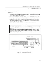
Page 17: ...A08531 3 When using the LID SIGNAL function of the 12704A connect the LID SIGNAL IN PUT on the rear panel of the 8340A to the LID SIGNAL connector of the 12704A by using the BNC BNC cable A01036 4 Fix the short bar of the 8340A between the GND GUARD and LO terminals The 8340A outputs applied voltage of maximum 1000 V Perform measurement with great care If a cable is disconnected with voltage being...

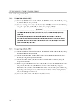
Page 18: ...e Be sure to set the voltage STANDBY before disconnecting the cable 3 1 3 Connecting with the 8252 1 Connect the INPUT terminal of the 8252 to the INPUT terminal of the 12704A by using the TRIAX TRIAX cable A01009 2 Connect the HI OUTPUT terminal of the 8252 to the V SOURCE HI terminal of the 12704A by using the output cable A01044 3 Connect the LO terminal of the 8252 to the LO terminal of the 12...

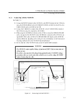
Page 19: ...GNAL connector of the 12704A by us ing the BNC BNC cable A01036 The INTERLOCK LID function of the 5450 5451 operates differently depending on the setting For more information on the function and its setting method refer to the 5450 5451 Operation Manual 4 Fix the short bar of the 5450 5451 between the LO and GUARD terminals The 5450 5451 outputs applied voltage of maximum 1000 V Perform measuremen...

Page 20: ...he electrodes will be damaged In such a case turn the switch to ON 1 M is added to measured values It takes longer time to reach a true value after measurement starts OFF If there is no possibility that a sample is short circuited turn the switch to OFF When the current limit of the V SOURCE is 10 mA or less and the generated volt age is 10 V or less measurement can be done with the switch set to ...

Page 21: ...ed values will vary 3 3 1 Calculating Volume and Surface Resistivities 1 When using the 8340A 8252 or 5450 5451 The 8340A 8252 or 5450 5451 has a function that calculates automatically the volume and surface resistivities For more information refer to the respective Operation Manual 2 When using a measuring instrument other than the 8340A 8252 and 5450 5451 Substitute measured values for the formu...

Page 22: ...hol 5 Replace the conductive rubber of the electrodes to new ones in the following cases A large scratch or crack occurs on the surface It is degenerated by chemical change such as sulfurization The degree of degeneration is judged by measuring the volume resistance of the elec trodes At this time mount the opposed electrode only without a sample If the measured value is 10 k or more replace the c...

Page 23: ...4 1 12704A Resistivity Chamber Operation Manual 4 Specifications Chapter 4 Specifications ...

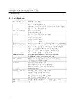
Page 24: ...assis guard opposed electrode 1 109 or higher Opposed electrode guard electrode 1 109 or higher Main electrode chassis 1 1014 or higher Dielectric strength Main guard opposed electrode 1000 VDC for a minute All electrodes chassis 1100 VDC for a minute Safety function LID signal contact signal to be set open at cover opening Cover interlocking VS OFF switch Connector Input terminal triaxial connect...

Page 25: ...A 1 12704A Resistivity Chamber Operation Manual APPENDIX APPENDIX ...

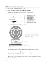
Page 26: ...se values for formulas 1 and 2 Volume resistivity t Rv 63 19 v cm 3 Surface resistivity Rs 84 18 s 4 By substituting measured values for formulas 3 to 4 the volume resistivity and the surface resistivity can be obtained v volume resistivity cm s surface resistivity Rv volume resistance Rs surface resistance circumference ratio 3 14 t sample thickness cm D guard electrode inner diameter cm d main e...

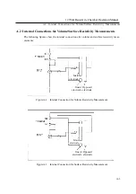
Page 27: ...ce Resistivity Measurements The following figures show the internal connections for volume and surface resistivity meas urements Figure A 2 Internal Connection for Volume Resistivity Measurement Figure A 3 Internal Connection for Surface Resistivity Measurement Main electrode Guard electrode Opposed electrode Main electrode Guard electrode Opposed electrode ...

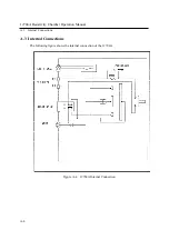
Page 28: ...A 4 12704A Resistivity Chamber Operation Manual A 3 Internal Connections A 3 Internal Connections The following figure shows the internal connection of the 12704A Figure A 4 12704A Internal Connection ...

Reviews: