


10
American Dryer Corp.
113279 - 9
NOTE 1 Opening from combustible materials must be 2-inches (5.08 cm)
larger than the duct (all the way around). The duct must be centered
within this opening.
NOTE 2 Distance should be 2 times the diameter of the duct to the nearest
obstruction.
Multiple Dryer (Common) Venting
IMPORTANT: For extended ductwork runs, the cross-
sectional area of the ductwork can only be increased to an
extent. When the ductwork approaches the maximum
limits as noted in this manual, a professional HVAC firm
should be consulted for proper venting information.
If it is not feasible to provide separate exhaust ducts for each
dryer, ducts from individual dryers may be channeled into a
“common main duct.” The individual ducts should enter the
bottom or side of the main duct at an angle not more than
45º in the direction of airflow. The main duct should be
tapered, with the diameter increasing before each individual
duct is added.
IMPORTANT: Exhaust back pressure measured by a
manometer/magnehelic in the exhaust duct must be no
less than 0 and must not exceed 0.6 in WC (1.5 mb).
NOTE: It is recommended that exhaust or booster fans not
be used in the exhaust ductwork system except where
necessary to maintain exhaust back pressure (in the
exhaust duct) between zero and 0.6 in WC. Where
employed, booster fans must not activate the dryer airflow
proving switch (sail switch) when the dryer is not in
operation.
When the exhaust ductwork passes through a wall, ceiling,
or roof made of combustible materials, the opening must
be 2-inches (5.08 cm) larger than the duct (all the way
around). The duct must be centered within this opening.
As per the National Fuel Gas Code, “Exhaust ducts for
type 2 clothes dryers shall be constructed of sheet metal or
other noncombustible material. Such ducts shall be
equivalent in strength and corrosion resistance to ducts
made of galvanized sheet steel not less than 26 gauge
(0.0195-inches [0.50 mm]) thick.”
The ductwork for this appliance must be suitable for the
appliance category in accordance with national installation
regulations of the country of destination.
Outside Ductwork Protection
To protect the outside end of the horizontal ductwork from
the weather, a 90° elbow bent downward should be installed
where the exhaust exits the building. If the ductwork travels
vertically up through the roof, it should be protected from the
weather by using a 180° turn to point the opening downward.
In either case, allow at least twice the diameter of the duct
between the duct opening and the nearest obstruction (refer
to the diagram).
IMPORTANT: Do not use screens, louvers, or caps on the
outside opening of the exhaust ductwork.
Single Dryer Venting
IMPORTANT: For extended ductwork runs, the cross-
sectional area of the ductwork can only be increased to an
extent. When the ductwork approaches the maximum
limits as noted in this manual, a professional HVAC firm
should be consulted for proper venting information.
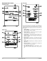
Horizontal Venting
When horizontal dryer venting is used, the length of the
ductwork from the dryer to the outside exhaust outlet, must
not exceed 20 feet (6.10 meters). The diameter of this
ductwork must be 4-inches (10.2 cm). Including tumbler/
dryer elbow connections or elbows used for outside protection
from the weather, no more than 1 elbow should be used in
the exhaust duct run. If more than 1 elbow is used, the cross-
sectional area of the ductwork must be increased.
Vertical Venting
When vertical dryer venting is used, the length of the ductwork
from the dryer to the outside exhaust outlet, must not exceed
12 feet (3.66 meters). The diameter of this ductwork must
be 4-inches (10.2 cm). Including tumbler/dryer elbow
connections or elbows used for outside protection from the
weather, no more than 3 elbows should be used in the exhaust
duct run. If more than 3 elbows are used, the cross-sectional
area of the ductwork must be increased.
A = 20 feet (6.10 meters)
B = 4” (10.2 cm)
C = 12 feet (3.66 meters)
D = 4” (10.2 cm)
Summary of Contents for AD22
Page 22: ...ADC Part No 113279 9 06 16 22 ...


