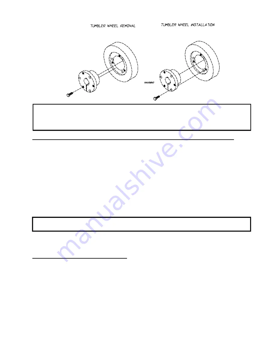
ADC AD-95 Service Manual Download Page 35

31

IMPORTANT:  

Tighten screws evenly and progressively.  Never allow the sheave to be drawn in

contact with the flange of the bushing.  This gap should measure from 1/8" to 1/4".
Proper cap screw torque is 30 ft-lbs.  If greater tightening forces are applied, excess
pressures will be created in the hub of the mounted sheave which may cause it to crack.

Tumbler Wheel Replacement on Idler Assembly (trantorque models)

1. Discontinue power to the dryer.

2. Remove the front panel form the dryer.  (Follow front panel replacement directions on page 27.)

3. Remove the ten (10) 1/4-20 x 1/4" socket button head screws from the perforated basket side.

4. Remove the wrapper assembly.

5. Block the basket (tumbler) assembly in position.

6. Mark the position of the pillow block bearings.  Then remove the bolts from the pillow block bearings.

7. Remove the idler shaft assembly through the front of the machine.

8. Remove the transtorque from the wheel assembly.

NOTE:

  One wrench must be on the transtorque and one on the axle.  The wrench on the transtorque

should have pressure applied in a counterclockwise direction.

9. Remove the bushing (transtorque) and tumbler wheel.

10. Reverse these procedures for replacement.

To Replace Blower Shaft Pulley

1. Discontinue power to the dryer.

2. Remove the ten (10) 1/4-20 x 1/4" socket button head screws from the perforated basket side and remove

the basket panel.

3. Remove the inside right wrapper.

4. Loosen v-belts.  Rotate pulley and roll v-belts out of the groove.

5. Remove cap screw from bushing.

6. Insert cap screws in tapped removal holes and tighten evenly until bushing becomes loose on shaft.

7. Remove bushing, pulley and key.

8. Reverse this procedure for replacement.

Summary of Contents for AD-95

Page 1: ...AmericanDryerCorporation 88 Currant Road Fall River MA 02720 4781 Telephone 508 678 9000 Fax 508 678 9447 E mail techsupport amdry com 072298SL cj ADCPartNo 450188 AD 95 ML 95 Service Manual...

Page 2: ...ent location near the dryer American Dryer Corporation products embody advanced concepts in engineering design and safety If this product is properly maintained it will provide many years of safe effi...

Page 3: ...UPERVISED IF NEAR DRYERS IN OPERATION DRYERS SHOULD NEVER BE LEFT UNATTENDED WHILE IN OPERATION CAUTION FOR YOUR SAFETY DO NOT DRY MOP HEADS IN THE DRYER DO NOT USE DRYER IN THE PRESENCE OF DRY CLEANI...

Page 4: ...he equipment and or specified in the installation and operator s manual included with the dryer Dryers must not be installed or stored in an area where it will be exposed to water or weather The wirin...

Page 5: ...for Gas Models ONLY 10 D GasBurnerAssembly 10 E Drive Motor 11 F Blower Motor and Impellor 11 G DriveShaftAssembly 12 H IdlerShaftAssembly 13 I Basket Tumbler 14 J Main Door Switch 14 K Sail Switch fo...

Page 6: ...stics 41 A Diagnostic L E D Display Failure Codes 41 B LED Display Indicators 43 C L E D Codes 48 D Computer Logic and Wiring Diagram 50 SECTION VIII Technical Information 56 A Motor Plate High and Lo...

Page 7: ...ly textured rubberlike materials Drying in a heated tumbler may damage plastic or rubber and also may be a fire hazard 5 A programshouldbe established for the inspection and cleaning of lint in the bu...

Page 8: ...own for average usage which is considered six 6 to eight 8 operational running hoursperday Clean lint drawer and screen every third load NOTE Frequency can best be determined at each location Daily be...

Page 9: ...or cleaning appliances is recommended B Adjustments Seven Days after Installation and every 6 Months Inspect bolts nuts screws bearing set screws nonpermanent gas connections union shut off valves ori...

Page 10: ...e from overheating The air supplymust be given careful consideration to insure proper performance of each dryer IMPORTANT Makeup air must be provided from a source free of dry cleaning fumes Makeup ai...

Page 11: ...nd display will show dRYING MANUAL CYCLE 30 MIN REMAIN then display the drum temp NOTE Pressing touch pads A B C D and F will also start the dryer Six 6 preprogrammed drying cycles A through F have be...

Page 12: ...the control panel will allow access to themajorcomponentswhichincludethecomputerboard and keypad The keypad inputs to the computer what temperature and program has been selected The com puter controls...

Page 13: ...ed on the back of the relay box is the revers ing relay panel Included on this panel is a four 4 posi tion terminal block blower overload blower contactor reversing contactor 24VAC transformer fuse or...

Page 14: ...s Models Only The HSI system consists of a microprocessor based control module along with a hot surface ignitor probe and a flame probe assembly The hotsurfaceignitorisasiliconcarbideignitorthat upon...

Page 15: ...or down forward or backward The drive motor is a 1 2 HP motor and operates on 208 to 460 volts 50 60 hertz 3 phase F Blower Motor and Impeller The impeller is shaft driven The blower mo tor drives the...

Page 16: ...f the dryer you can view the drive shaft assembly which consists of a 9 drive pulley two 2 6 wheels two 2 trantorques onmodelsmanufacturedprior to December 15 1997 or with two 2 taperlock bear ings on...

Page 17: ...sideofthedryeryouwillviewthe idler shaft assembly which consists of two 2 6 wheels two 2 transtorque on models manufactured prior to December 15 1997 or with two 2 taperlock bearings on models manufac...

Page 18: ...reventingthedryerfrom operating The main door switch is a safety device and should never be disabled I Basket Tumbler The basket consists of a basket tumbler weldment which have four 4 ribs and four 4...

Page 19: ...makeup air L Hi Limit Gas Models Only Prior to May 26 1998 The high limit thermostat is an automatic reset disc type thermostat set at 330 Fand located near the burner If the burner flame gets too ho...

Page 20: ...e dryer will not heat If the temperature sensor opens the display will read TEMP SENSOR FAIL CHECK TEMP SEN SORFUSE withanaudioindication Ifthether mostat opens the display will read dRUM SAFETY FAIL...

Page 21: ...witch is located in the lint compartment and at tached to the side of the lint coupe The lint door switch ensures that the dryer will operate only when the lint door is completely closed This is a saf...

Page 22: ...puter panel by squeezing the clip on the pin connector and pulling the plug away from the board 3 Disconnect the green ground wire from the board 4 Disconnect the ribbon cable assembly from the input...

Page 23: ...ntinue power to the dryer 2 Open lint door 3 Remove microprocessor sensor bracket assembly from dryer a Disconnect sensor bracket harness connector b Loosen the two 2 Phillips head screws which secure...

Page 24: ...red wire from the flame sensor probe which goes to S2 on the HSI module 3 Disassemble flame sensor probe from burner by removing the one 1 self tapping screw 4 Reverse procedure for installation of n...

Page 25: ...installing NOTE Test all connections for leaks by brushing on a soapy water solution NEVER TEST FOR LEAKS WITH A FLAME To Test and Adjust Gas Water Column Pressure There are two 2 types of devices com...

Page 26: ...extreme care when removing orifices They are made of brass and are easily damaged 3 Reverse the procedure for reinstalling valve assembly to the dryer WARNING Test all connections for leaks by brushi...

Page 27: ...tured as of 1998 are equipped with a manual reset hi limit thermostat 1 Discontinuepowertodryer 2 Disconnect wires from hi limit thermostat 3 Remove the two 2 screws washers and nuts securing thermost...

Page 28: ...ail switch open main door manually depress main door switch and start dryer With the main door open and the dryer operating the sail switch should be open and the burner should not come on 4 Remove br...

Page 29: ...s should the door switch be disabled To Replace Main Door Assembly 1 Open main door 2 Holding the door upward remove the two 2 screws from the top hinge block 3 Lift the door up to remove 4 Reverse th...

Page 30: ...at least 24 hours Depending on the conditions the curing time of this adhesive is 24 to 36 hours 7 After 24 hour curing period install main door on dryer by reversing step 1 IMPORTANT Do not press har...

Page 31: ...oneiscuredyoumaywanttotrimanyexcesssiliconeontheinsideofthemaindoor assembly 6 After the curing period install the main door on the dryer by reversingstep 1 To Replace Front Panel 1 Discontinue power...

Page 32: ...belt out of groove 4 Remove set screw from the drive motor pulley 5 Remove pulley and key NOTE A gear puller may be required to remove pulley 6 Reverse this procedure for replacement NOTE Pulleys must...

Page 33: ...t to crack Tumbler Wheel Replacement on Drive Assembly transtorque models 1 Discontinue power to dryer 2 Remove front panel from the dryer Follow front panel replacement directions on page 27 3 Remove...

Page 34: ...panel replacement directions on page 27 3 Remove the ten 10 1 4 20 x 1 4 socket button head screws from the perfed basket side 4 Remove the wrapper assembly 5 Block the basket tumbler assembly in posi...

Page 35: ...illow block bearings Then remove the bolts from the pillow block bearings 7 Remove the idler shaft assembly through the front of the machine 8 Remove the transtorque from the wheel assembly NOTE One w...

Page 36: ...ey and roll v belts out of groove 5 Remove cap screws from the bushings 6 Insert cap screws in tapped removal holes and tighten evenly until bushing becomes loose on shaft 7 Remove bushing pulley and...

Page 37: ...on and tighten set screws 6 Refer to basket assembly section page 32 for shaft and basket alignment To Replace Drive Assembly Pillow Block Bearing 1 Refer to tumbler wheel replacement on drive assembl...

Page 38: ...power to dryer 2 Remove front panel from dryer Follow front panel replacement instructions on page 27 3 Remove drive belt 4 Disconnect wiring harness from motor 5 Remove bolts holding motor to mount a...

Page 39: ...igned 9 Remove the old motor from the motor mount and install the new motor on the mount 10 Reconnect the wiring harness to the motor 11 Install motor mount assembly back into the dryer and replace bo...

Page 40: ...yer 2 Remove thruster wheel cover 3 Remove the two 2 bolts securing the thruster wheel bracket to the rear of the machine 4 Remove the nut securing the thruster wheel to the bracket and remove the thr...

Page 41: ...ews from the lint screen frame NOTE It may be easier to remove a perforated basket panel for easier access to the lint screen screws 4 Replace lint screen and secure frame to the lint coupe 5 Close li...

Page 42: ...cal Troubleshooting for a detailed troubleshooting procedure for electrical components 1 No display on computer A Open circuit breaker switch or blown fuse B Tripped blower motor overload C Badwiringc...

Page 43: ...e blocked with lint D Failed motor E Failed overload F Out of balance impeller fan G Insufficient makeup air 10 Overload for impeller fan motor is tripping A Either an exceptionally low or high voltag...

Page 44: ...reads main door or lint door with an audio indication A Maindoorisopen B Lint drawer is open C Faulty main door or lint door switch D Open circuit in either main door or lint drawer switch harnesses E...

Page 45: ...tine monitors the tumbler temperature if the tumbler Hi Limit switch opens prior or during the cycle while the heat was on the machine will display dRUM SAFETY FAIL The machine will continue to run wi...

Page 46: ...ey and it will continue the programmed cycle 10 TEMP SENSOR FAIL CHECK TEMP SENSOR FUSE This routine monitors the tumbler temperature When the temperature sensor or fuse opens with the machine not act...

Page 47: ...n progress These indicator dots as shown in the illustration below do not necessarily mean that the outputs are functioning They are only indicating that the function output should be active on 1 L E...

Page 48: ...are identified or labeled from top to bottom in the illustration below as FAN BLOWER FOR FORWARD REV REVERSE AIR AIR JET HT1 HEAT OUTPUT There are a series of seven 7 L E D indicators red lights FUSE...

Page 49: ...mbler motor is not yet the Phase 6 OPL microprocessor controller computer displays REVERSE indicator dot is on but the REV REVERSE motor output L E D is off then the fault is of the Phase 6 OPL microp...

Page 50: ...r A Should be on at ALL times unless the tumbler hi limit switch opens prior during the cycle while the heat was on the display would read dRUM Safety FAIL The machine will run with no heat for three...

Page 51: ...ER CONTROL FAIL The machine will run with no heat for three 3 minutes or until the temp drops below 100 F Then the machine will shut down still displaying bURNER CONTROL FAIL with an audio indication...

Page 52: ...TEMPERATURE PREPROGRAMMED CYCLE A PREPROGRAMMED CYCLE B PREPROGRAMMED CYCLE C PREPROGRAMMED CYCLE D PREPROGRAMMED CYCLE E PREPROGRAMMED CYCLE F DRYING or COOLING CYCLE COMPLETE OR DRYER IN ANTI WRINK...

Page 53: ...ndicates an OVERHEAT CONDITION LINT dOOR When the LINT DOOR OR DRAWER is open or there is a fault in the LINT DOOR DRAWER CIRCUIT MAIN dOOR When the MAIN DOOR is open or there is a fault in the DOOR C...

Page 54: ...e This number is located on the top right hand corner of the diagram It is a six 6 digit number followed by a letter to distinguish the revision dates see illustration The wiring diagrams used in trou...

Page 55: ...e across fuses 1 and 2 to ground If voltage is present check emergency stop red and black wire to ground If voltage is present check voltage across 95 and 96 to ground of the drive motor overload If v...

Page 56: ...re is voltage replace the coil or the complete contactor If there is no voltage check for voltage across the two BS3 terminals on the arc suppressor board If there is voltage across the two BS3 termin...

Page 57: ...0 and 21 D If no voltage is present at J7 9 pin connector no 3 to ground then voltage should not be present at no 5 to ground Replace the board 6 Main Door Condition NOTE Makesuremaindoorandlintdoorar...

Page 58: ...g J3 4 pin connec tor from the temperature sensor bracket Also unplug the microprocessor J14 4 pin connector from the computer board Take a continuity reading from J14 no 1 to J3 no 1 then from J14 no...

Page 59: ...re is above 100 F the dryer will continue to run with no heat for three minutes or until the drum temperature has fallen below 100 F The clear and stop button on the Phase 6 keypad must be pressed to...

Page 60: ...ge ratings Removing the cap reveals the wiring to the motor On each wire there is a number which corresponds to the numbers on the motor plate Depending on whether the dryer is operating on low or hig...

Page 61: ...scribes the size of the dryer and the type of heat gas or steam B Serial number The serial number allows ADC to gather information on your particular dryer C Manufacturing code number The manufacturin...

Page 62: ...ce manometer in a position so that readings can be taken at eye level 4 Fill manometer with water as shown in illustration to the zero level 5 Start dryer With burner on take a reading A Read water le...

Page 63: ...3 8 Socket Wrench 1 2 Socket or Open End Wrench 1 4 Open End Wrench 5 16 Socket or Open Wrench 1 2 Socket Wrench 7 16 Socket or Open End Wrench 5 16 Nut Driver 12 Pipe Wrench 2 1 8 T Shaped or L Shap...

Page 64: ...ADC 450188 1 01 14 99 25 2 09 15 99 25...

Reviews: