Installation
LTPH-UM-1088-02, Issue 2
6
January 3, 2002
ThinMux Chassis
M
OUNTING THE
C
HASSIS
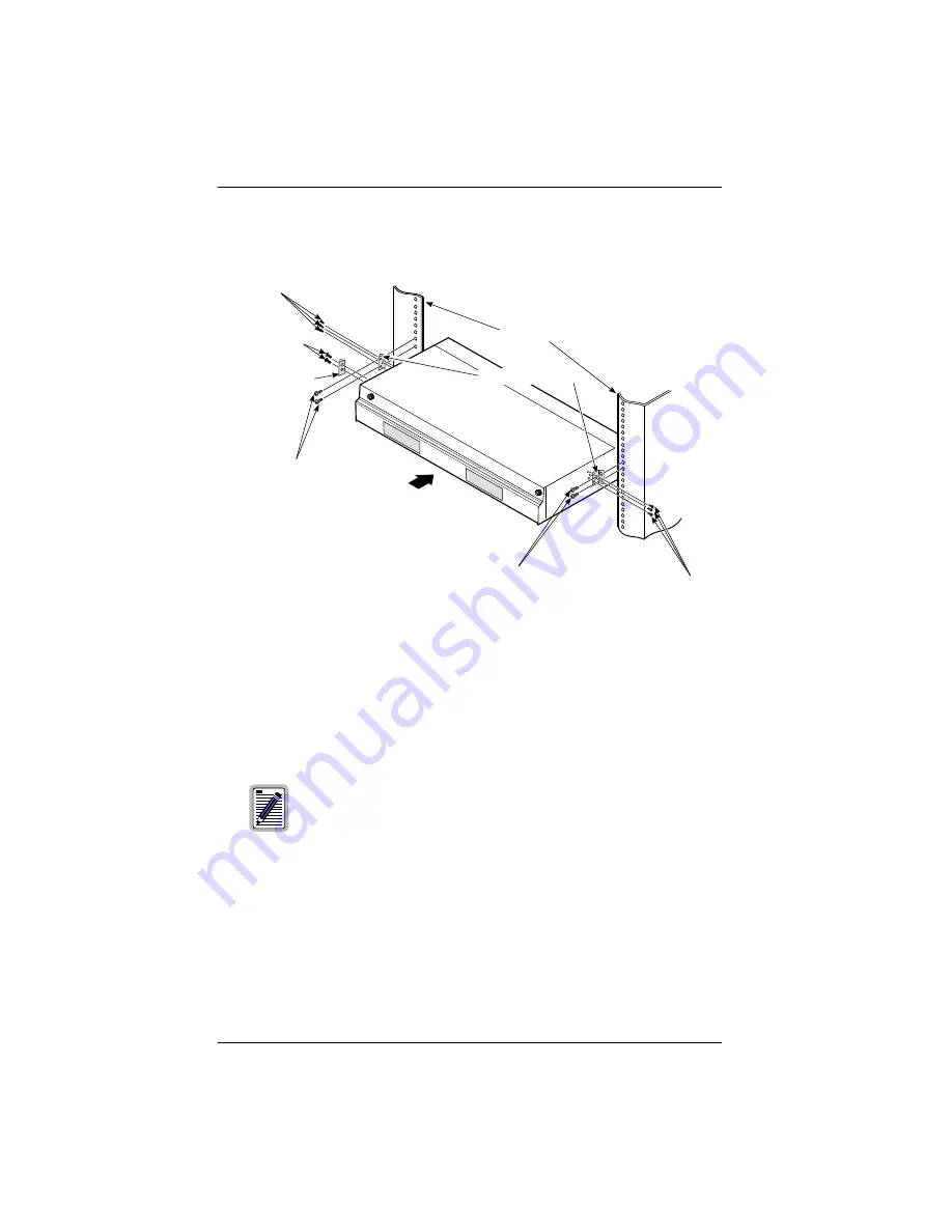
Figure 2.
ThinMux Chassis in a CO Rack
1
Install a mounting bracket on each side of the ThinMux chassis using the
three screws provided for each bracket (8-32 x
5
/
16
screws) as shown in
. (Mounting brackets and screws are contained in the installation
kit.)
2
Install ESD input bracket on front left side of the chassis.
3
Align the chassis mounting bracket holes with the rack’s vertical
mounting holes. Mount the chassis in the rack. Install two
12-24 x
1
/
2
screws in each bracket and secure the chassis to the rack.
Two sets of mounting brackets are supplied to fit 19-inch or
23-inch racks with standard EIA-hole spacing (1/2 inch).
Optional brackets with WECO-hole spacing (1 inch) are
available (ACE-MK1).
CO rack
Two 12-24 x / screws
1
2
Three 8-32 x / screws
5
ESD input bracket
Two 6-32 x / screws
1
4
Three 8-32 x / screws
5
16
Mounting brackets
Two 12-24 x / screws
1
2
16
Summary of Contents for ACE-COM L1
Page 1: ...USER MANUAL ThinMux Chassis Product Catalog ACE COM L1 Part Number 150 2263 01 CLEI VAMXHN0F...
Page 8: ...List of Tables LTPH UM 1088 02 Issue 2 viii December 7 2001 ThinMux Chassis...
Page 10: ...List of Tables LTPH UM 1088 02 Issue 2 x November 7 2001 ThinMUX Chassis...
Page 33: ......


