150-712-200-02
Appendix A - Technical Reference
HRE-712 List 1 and List 2
July 26, 2000
19
A
PPENDIX
A - T
ECHNICAL
R
EFERENCE
Appendix A contains additional technical information about the HRE-712 List 1 and List 2 enclosures.
C
ARD
C
AGE
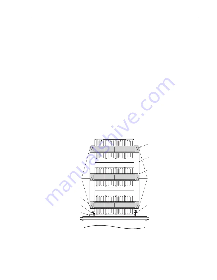
The card cage inside each enclosure, shown in
, has 12 mounting positions for doublers and repeaters.
They are front loading, arranged in three rows of four slots each. Each row has its own retainer bar which serves
two purposes:
•
The circuit ID of each slot can be written on the label attached to each retainer bar.
•
The retainer bar prevents the cards from disconnecting when the enclosure is subjected to severe vibrations.
You can access the doublers by loosening the side wing nuts and rotating the retainer bar. The enclosure has a
mechanism that enables the card cage to tilt up approximately 45° to allow easy access to the rear of the card cage
in case LPU board service is needed. Two knobbed retainer screws at the base of the card cage (one on each side)
lock the card cage in its normal level position and prevent it from tilting during severe vibrations. The cable stubs
shield is grounded to the card cage base through a short braided wire. This braided wire should be disconnected
if the enclosure stub’s shield is bonded to the shield of the main feeder cable. This breaks the ground loop created
by connecting the two cable shields and prevents circulating ground currents from possibly causing service
affecting noise.
The card cage grounds through a ribbon ground connection between the base of the card cage and its side.
Figure 7.
Front View of HRE-712 12-slot Card Cage
Stub shield
braded grounding strap
Card cage release knob
Retaining bar release
knobs
Retaining bar
Retaining bar
Card cage
Retaining bar
Retaining bar release
knobs
Card cage release knob
9
5
1
6
2
7
3
8
4
10
11
12


