


150-425-100-04
HRE-425 List 1
September 22, 1999
7
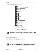
Figure 5.
HRU Pin Assignments
F
USE
A
LARM
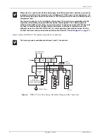
Each of the 12 slots come equipped with a 0.5 Amp fuse between the 48 Vdc shelf supply and pin 35 as shown in
. This accommodates the maximum power consumption requirements when using the HRE-425
to house HLU-431 line units.
All the fuse alarm contacts are transmitted together on one bus and connected to the Fuse Alarm, pin 3 of TB1. If
a fuse opens, the normally floating Fuse Alarm in pin 3 drives to -48 V.
There is a shock hazard to craft personnel as a result of contact with a case that may have
floated to an unsafe voltage. Properly ground the case to avoid shock hazard.
Damage to the HRU circuits may result if the discharge path to earth ground for its secondary
surge voltage protection components is missing. Connect pin 4 of TB1 to earth ground to avoid
HRU damage (see
In unusual noise environments, it may be necessary to connect the HRUs circuit ground Pin 17
to frame ground Pin 1 of the card-edge connector to remove bit errors from the T1 payload (see
).
27
25
23
21
19
17
15
13
11
9
7
3
5
1
DS1TIP
DS1 RING
HDSL2 RING1
HDSL2TIP 1
RS-232 DATA OUT
-48V
CIRCUIT GROUND
FOR FACTORY TESTING
DS1 RING1
HDSL1 RING
XMT
RCV
HDSL1TIP
DS1TIP
CHASSIS GROUND*
28
26
24
22
20
18
16
14
12
10
8
4
6
2
55
53
51
49
47
45
43
41
39
37
35
32
31
56
54
52
50
48
46
44
42
40
38
36
34
30
33
29
Note: Active pins are highlighted in black
RS-232 DATA IN
48V LOCAL
POWER SUPPLY
H0336-A