background image

Page 19
Rev. : 002

HF - VISION 10 & PHOENIX

Lighting Technologies

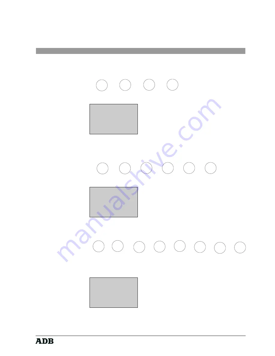
Change the hours from 0 to 23 via the up and down keys. Confirm with the key
MENU
Key sequence:

Display :


10:15

Minutes: 0

UP & DN TO SEL.

Change the minutes from 0 to 59 via the up and down keys. Confirm with the key
MENU

Key sequence:

Display :


10:15

Seconds: 0

UP & DN TO SEL.

Change the seconds from 0 to 59 via the up and down keys. Confirm with the key
MENU
Key sequence:

The new time is now set and you are back in the standard menu.

Display :


10:15

M E N U     v1.0

1 MODE

3 ID

2 ROOM

4 ADJ

SELECT A NUMBER

MENU

FF

UP
DN

MENU

UP
DN

MENU

MENU

FF

UP
DN

MENU

UP
DN

MENU

UP
DN

MENU

MENU

FF

UP
DN

MENU

Summary of Contents for PHOENIX

Page 1: ...Page 1 Rev 002 HF VISION 10 PHOENIX Lighting Technologies HF Remote Control for VISION 10 and PHOENIX Lighting Technologies Instruction Manual ME 2103 1106 02 103 ...

Page 2: ...Page 2 Rev 002 HF VISION 10 PHOENIX Lighting Technologies ...

Page 3: ...ode 21 6 3 2 Command Line Mode 21 6 4 Display Key History List 22 6 5 Special key functionalities 23 6 5 1 The SHIFT key 23 6 6 Switch OFF 23 7 Resetting the transmitter 24 8 Technical Characteristics 25 9 The Satellite Control Center Software 26 9 1 Before installation 26 9 2 Installating the software 26 9 2 1 SCC Set up 26 9 3 Starting SCC 28 9 4 Main Screen 28 9 5 Configuration 29 9 5 1 Configu...

Page 4: ...ions and this during an operating period of up to 12 hours with one battery charge cycle The GSM size hand held system is very easy to handle and allows fast and intuitive access to a huge variety of key desk functions to allow you to work efficiently on your lighting show After a quick start tour that briefly describes how fast to access the basic lighting functions you will find in the following...

Page 5: ...se and to check the equipment connected to it To obtain full benefits of the safety measures the equipment shall be installed and serviced by skilled and trained personnel exclusively Don t make any modification to the equipment ADB shall not accept any liability for material damages or injuries which may result from unauthorised modifications Important Notice for Power Cables Power supply cables ...

Page 6: ...g kit Battery Charger BCHF V 6172 30 030 containing ext 9V psu Multiple Communication up to 4 receivers 50 80m item code adb code number Transmitter 734A EMHF V 6382 01 400 SAT Receiver RS485 REHF2 V 6382 01 420 containing ext 9V psu t connector box RS485 cable T box SAT 6m wall mounting kit Converter RS485 RS232 CONHF V 6382 01 430 containing ext 9V psu RS232 cable RJ45 DB9 2m T BOX cable to conv...

Page 7: ...ply will be distributed over the cable from the serial line connector to the HF receiver com port 4 1 3 Installation with more than one HF Receiver This configuration permits to extend the operating range to more than 50 80 meters by interconnecting up to 4 HF receivers For technical communication reasons a separate standard PC with a 32 bit WINDOWS version and a RS232 485 protocol converter have ...

Page 8: ...ceivers to be connected to a standard serial RS232 communication port of a PC The PC takes over all communication between the different devices and sends the commands via an RS232 NULLMODEM cable to the lighting desk Sender HF communication Receivers max 4 Control desk RS485 cable RS485 cable RS485 cable RS485 cable RS485 cable SYSNET T box w psu T box w psu T box w psu T box w psu RS485 cable SYS...

Page 9: ...mally located besides the floppy drive Room ID 1 see also further explanations below Product ID 1 see also further explanations below If these settings shall be changed on your control desk system create a DOS file hf cfg in the path c vision10 containing the following parameter settings Example system connected to 2nd serial communication port room number 2 and product identification number 1 VIS...

Page 10: ...P GRP select group of channels 10 through select range of values MEM MEM select memory 11 SHIFT N A activate shift functions N A N A N A 12 7 7 value 7 M7 M7 call macro 7 13 8 8 value 8 M8 M8 call macro 8 14 9 9 value 9 M9 M9 call macro 9 15 4 4 value 4 GO GO1 start playback 1 16 5 5 value 5 BCK BCK1 go back in playback 1 17 6 6 value 6 CUT CUT1 cut transfer of playback 1 18 1 1 value 1 TST TST N ...

Page 11: ...RD was used to select a password i e if the current password selected is not 0000 see chapter MENU Display 10 15 ADB PASSWORD _ _ _ _ The first display line is a status line indicating the battery charge level and the current time You first have to introduce your password that can be a combination of up to 4 numbers 0 9 Display If the password is not correct the start up screen reappears Display 1...

Page 12: ...ry type in the digit combination 9999 twice If the password is correct or if no password was formerly selected activated via the menu password 0000 the standard display screen appears Thestandardscreen emptyatfirstpower upasnodeskcontrolcommandsenteredsofar Standard Display 10 15 The four horizontal text display lines show a history list representing the key sequence that has so far been introduce...

Page 13: ...quence Display II 11 15 M E N U v1 0 1 MODE 4 ADJUST 2 ROOM 5 TERMID 3 PRID 6 BEEP The menu display page shows a title MENU and the current software version Via the buttons 1 6 you can select several sub menus following the above mentioned menu structure All selections done in the menu have default factory settings When you change the parameter values these changes remain active even after switchi...

Page 14: ...bove shown example Default is direct mode Toggle between the two modes by using the keys up and down 6 2 1 3 Room Number Key sequence Display 10 15 MENU MENU EXIT ROOM No 1 UP DN TO SEL As HF signals can easily pass through walls and as two different rooms can be located very close to one another every room can be allocated its own virtual room number between 1 and 16 A user operating a hand held ...

Page 15: ...6 by using the keys up and down 6 2 1 5 Adjustments Key sequence Display 10 15 MENU v1 0 ADJUSTMENTS 1 LITE 3 SLEEP 2 CONTR 4 PASSW Several parameters can be adjusted via the sub menu item Adjustments 6 2 1 5 1 Adjustments Display Back light Key sequence Display 10 15 MENU MENU EXIT ADJUSTMENTS BACK LIGHT ON UP DN TO SEL This sub menu is used to switch the display s back light ON or OFF Please not...

Page 16: ...sequence Display 10 15 MENU MENU EXIT ADJUSTMENTS AUTO SLEEP 2 UP DN TO SEL This sub menu is used to enable and disable an auto sleep timer and assign operating times in minutes The auto sleep mode can be altered between 0 and 5 minutes by the use of the keys up and down If 0 is selected auto sleep modus is off in this case the remote control unit would remain on until the internal battery is too ...

Page 17: ...hand On the other hand it may cause problems when you are obliged to often change the password If currently any password selection is active you first have to type in your current password of up to 4 digits 0 9 The equivalent of no password is 0000 four zeros If no password is selected the password procedure is skipped after the switch on procedure Keys that are pushed are not shown on the display...

Page 18: ...isplay 10 15 MENU MENU EXIT ADJUSTMENTS CONFIRM PASSW _ Default is value NO PASSWORD 0000 6 2 1 5 5 Setting the time It is possible to change the time via a menu function Therefore the menu has to be activated Key sequence Display II 11 15 M E N U v1 0 1 MODE 4 ADJUST 2 ROOM 5 TERMID 3 PRID 6 BEEP The time can now be set by pushing on the key FF Key sequence Display 10 15 Hour 0 UP DN TO SEL MENU ...

Page 19: ... 59 via the up and down keys Confirm with the key MENU Key sequence Display 10 15 Seconds 0 UP DN TO SEL Change the seconds from 0 to 59 via the up and down keys Confirm with the key MENU Key sequence The new time is now set and you are back in the standard menu Display 10 15 M E N U v1 0 1 MODE 3 ID 2 ROOM 4 ADJ SELECT A NUMBER MENU FF UP DN MENU UP DN MENU MENU FF UP DN MENU UP DN MENU UP DN MEN...

Page 20: ...connected This function is optional and is only of use when several satellites are connected to several desks You can increase the number up to 100 by using the keys up and down Default terminal ID is 1 6 2 1 7 Beep Key sequence Display II 11 15 M E N U M E N U EXIT ADJUSTEMENTS BEEP ON UP DN TO SEL This sub menu is used to switch the acustical key click and the send feedback signal ON or OFF When...

Page 21: ...ts the communication set up procedure after 30 seconds If you do not want to wait so long leave the procedure by pushing on CLear 6 3 2 Command Line Mode If the operation mode COMMAND LINE is chosen via MENU MODE COMMAND LINE any key sequence has to be confirmed via the key SEND before it is sent to the desk Whenever the button SEND is pushed to send the whole key sequence of up to the whole displ...

Page 22: ...aving one space character in between and the new button function abbreviation is displayed instead Example setting channel number 123 at 72 intensity Key sequence 1 2 3 AT 7 2 Standard Display 10 15 1 2 3 AT 7 2 When the line is full the upper lines are used Key sequence 1 2 3 AT 7 2 CL CL MEM 1 CL CL MEM 2 CL Standard Display 10 15 1 2 3 AT 7 2 CL CL MEM 1 CL CL MEM 2 CL If all lines are filled t...

Page 23: ...y interpreted as defined in the SHIFT table see chapter QUICK START Example Activate macro 8 and macro 9 key button sequence SHF 8 SHF 9 Standard Display 10 15 M8 M9 Pushing the SHIFT key does not make any symbol appear on the screen but the built in LED lights up in orange indicating the SHIFT mode Using the SHIFT key does not generate any HF message for the desk 6 6 Switch OFF The transmitter ca...

Page 24: ...on the front panel between the ARROW LEFT and the LED and push on the MENU key simultaneously while holding the object in the hole The following screen appears Standard Display 10 15 PROGRAM ERASE 5 NO 3 YES Caution Be sure that you answer the question about erasing the program with 5 NO Waiting some seconds will cause the system automatically resetting the device without erasing the program equal...

Page 25: ...W Transmission speed 9600 bit sec Protocol RS232 Display back lit 4 x 16 characters Batteries rechargeable 200mAh Ni Cd Battery Battery charging via external charging unit Autonomy up to 12 hous Water and dustproof characteristics IP65 Protection against electrostatic discharges up to 15KV Operating temperature 20 C to 50 C Dimensions 165 x56 x33 mm Weight 185g with battery Transmitter EMHF V Rece...

Page 26: ...C are issued in the same way as if a command is sent to a single receiver In short SCC operates as a single receiver but it collects and manages data from several receivers 9 1 Before installation Minimum configuration Pentium with 8 Mb RAM Windows 95 or Windows NT 10 Mb of free hard disk space Recommended configuration Pentium with 32 Mb RAM Windows NT 4 0 or higher Before installing Satellite Co...

Page 27: ...rive and directory The default directory is set to c Program Files Satellite Control Centre Of course you can alter the destination by clicking the Change Directory Button To continue installation of SCC to the specified location click the rather large button on the left 3 After all files have been successfully decompressed and copied and registry settings were accomplished setup is completed ...

Page 28: ...ollows Before you really start please take a look at all functionalities of the program After going through it you will be able to use SCC correctly and efficiently MENU Start program Stop program Data window Time Exit program About 9 4 Main Screen The main screen consists of a menu system push buttons and a status bar All menu functions are accessible through the main screen virtual push buttons ...

Page 29: ...mmunication settings have to be adapted to the computer s hardware profile This can be done via the menu item Configuration 9 5 1 Configuration Communication This configuration handles the serial communication between the SCC software and the lighting desk If your lighting desk is connected to the SCC PC s com port 2 copy the above shown settings otherwise adapt the com port to COM1 ...

Page 30: ...at Mark Sleep The waiting time in milliseconds between one terminal and the next The value 0 ensures maximum polling speed but drastically slows down the operation of other programs Time out The maximum waiting time for a reply from terminals or satellites expressed in milliseconds The safety value is 200 Depending on the specifications of the equipment in use this value can be reduced to fasten c...

Page 31: ... 10 PHOENIX Lighting Technologies 9 5 4 Terminals Senders As no data from the host is being sent towards terminals senders this section is irrelevant Do not alter anything on this screen 9 5 5 Satellites Receivers 9 5 5 1 Index ...

Page 32: ...rrelevant 9 5 5 3 3 Test echo Reserved for test procedures Irrelevant 9 5 5 3 4 Test RSSI Reserved for test procedures Irrelevant 9 5 5 4 Terminal from to Enter the first and last identifying number for the group of senders managed by the receiver If one sender must transfer data within the coverage range of different receivers its identifying number should be included in each group 9 5 5 5 Group ...

Page 33: ...fferent group numbers are given to adjacent receivers As a result when data transmission takes place between receivers A and E wich are not adjacent and the respective senders transmission between receivers B C D and F is disabled it then enables transmission from B and F and disables transmission from the other receivers and so on GROUP 1 GROUP 3 GROUP 1 GROUP 2 GROUP 4 GROUP 2 A C E B D F ...

Page 34: ...ose one of both methods 9 5 5 10 Separate Allows you to define the character that will separate the fields by inserting it directly or if the character does not appear on the keyboard by inserting the corresponding decimal value from the ASCII table 9 5 5 11 Set up Allows to send the properties defined to the terminal When you select this key the following dialogue box will appear prompting you to...

Page 35: ...s indicates Initialising If the initialisation of both ports was successful the status evolves from Idle towards Active If not an appropriate error message is being issued and status is set to Error During communication status can evolve from Active to Receiving Data and back to Active Notice that when SCC is active configuration settings are disabled You have to stop SCC through the menu Satellit...

Page 36: ...f SCC and also the possibility to have specific system information by pressing the System Info button 9 8 Exit Activating Exit by clicking the Exit button or by activating Exit from the Satellite menu exits SCC and closes all open ports and communication with all satellites If there is still data in the buffer no warning is issued the buffer is cleared and program execution is aborted ...

Page 37: ...B TTV Technologies S A makes no warranty of any kind with regard to this material including but not limited to the implied warranties of fitness for a particular purpose N V ADB TTV Technologies S A shall not be liable for errors contained herein or for incidental or consequential damages in connection with the furnishing performance or use of this material ...

Page 38: ...Page 38 Rev 002 HF VISION 10 PHOENIX Lighting Technologies Notes ...

Page 39: ...Page 39 Rev 002 HF VISION 10 PHOENIX Lighting Technologies Notes ...

Page 40: ...tem Tel 32 2 709 32 11 Fax 32 2 709 32 80 E Mail adb ttv adb be Internet www adblighting com Deutschland ADB GmbH Dieselstraße 4 D 63165 Mühlheim am Main Tel 49 6108 91 250 Fax 49 6108 91 25 25 E Mail adb lichtelek t online de Internet www adb deutschland de France ADB S A S 168 170 boulevard Camélinat F 92240 Malakoff Tel 33 1 41 17 48 50 Fax 33 1 42 53 54 76 E Mail adb adbfrance fr Lighting Tech...

Reviews: