www.adb-air.com
Airfield Lighting
Product Solutions Catalog
Users Manual
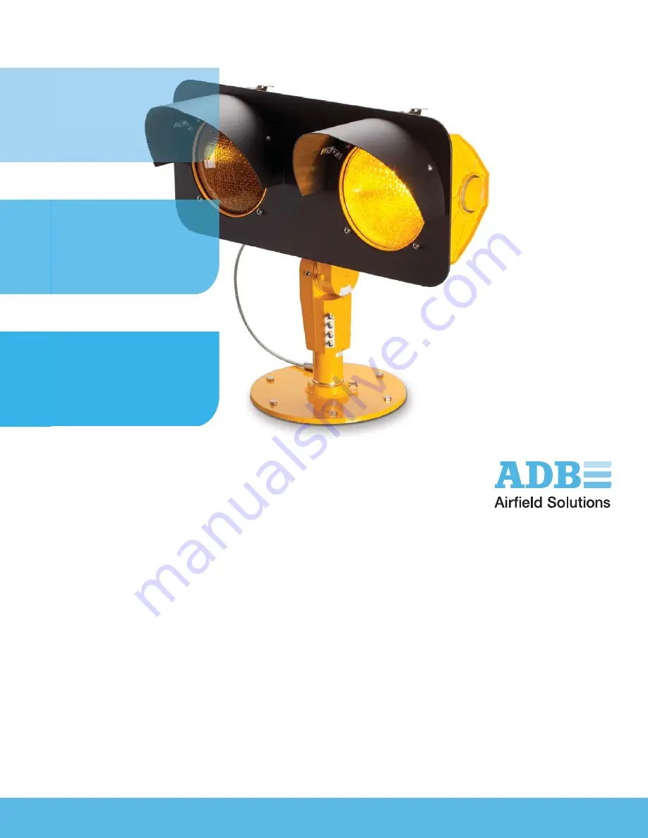
L-804 Elevated Runway Guard Light
Incandescent, Medium-Intensity ERGL
96A0218, Rev. X,
Page 1: ...www adb air com Airfield Lighting Product Solutions Catalog Users ManualUsers Manual L 804 Elevated Runway Guard Light Incandescent Medium Intensity ERGL 96A0218 Rev X ...
Page 2: ...years from date of installation per FAA AC 150 5345 44 applicable edition NOTE See your sales order contract for a complete warranty description A 5 All Products LED Products of ADB manufactured and sold by ADB or its licensed representatives meets the corresponding requirements of FAA ICAO and IEC ADB will correct by repair or replacement per the applicable guarantee above at its option equipment...
Page 3: ...ipment that have not been recommended or described in this manual or using parts that are not genuine ADB replacement parts or accessories Failing to make sure that auxiliary equipment complies with approval agency requirements local codes and all applicable safety standards if not in contradiction with the general rules Using materials or auxiliary equipment that are inappropriate or incompatible...
Page 4: ...ontents thereof without obligation of ADB BVBA to notify any person of such revision or change Details and values given in this manual are average values and have been compiled with care They are not binding however and ADB BVBA disclaims any liability for damages or detriments suffered as a result of reliance on the information given herein or the use of products processes or equipment to which t...
Page 5: ...tion 5 2 1 2 How to work with the manual 5 2 1 3 Record of changes 5 2 2 Product Introduction 6 2 2 1 Compliance with Standards 6 2 2 2 Uses 6 2 2 3 Electrical Supply 6 2 2 4 Operating Conditions 6 2 2 5 Equipment Specification Data 6 2 2 6 Dimensions 6 2 2 7 Required Equipment 7 2 3 Installation 8 2 3 1 Introduction 8 2 3 2 Inspection on Arrival 8 2 3 3 Installation Procedures 8 2 3 4 Installing ...
Page 6: ...Maintenance Schedule 16 2 4 2 Replacing Lamp 16 2 4 3 Replacing Lens 17 2 4 4 Adjusting Vertical and Horizontal Settings 17 2 5 Troubleshooting 18 2 6 Operation 19 2 6 1 Operation 19 2 7 Wiring Diagrams 20 3 0 Parts 25 3 1 Order Codes 25 3 1 1 Spare Parts List 25 3 2 RGL Major Components 26 ...
Page 7: ... ARC FLASH Disconnect equipment from line voltage Failure to observe this warning may result in personal injury death or equipment damage ARC Flash may cause blindness severe burns or death WARNING WEAR PERSONAL PROTECTIVE EQUIPMENT Failure to observe may result in serious injury WARNING DO NOT TOUCH Failure to observe this warning may result in personal injury death or equipment damage CAUTION Fa...
Page 8: ...ied by applicable safety regulations If safety devices must be removed for installation install them immediately after the work is completed and check them for proper functioning prior to returning power to the circuit Failure to follow these warnings may result in serious injury or equipment damage IMPORTANT INFORMATION IEC International Standards and Conformity Assessment for all electrical elec...
Page 9: ...n humid flammable or explosive environments unless it has been rated for safe operation in these environments Never touch exposed electrical connections on equipment while the power is ON Failure to follow this instruction can result in equipment damage CAUTION IMPROPER STORAGE If equipment is to be stored prior to installation it must be protected from the weather and kept free of condensation an...
Page 10: ...eath or equipment damage DANGER ARC FLASH AND ELECTRIC SHOCK HAZARD Allow only qualified personnel to perform maintenance troubleshooting and repair tasks Only persons who are properly trained and familiar with ADB Airfield Solutions equipment are permitted to service this equipment An open airfield current circuit is capable of generating 5000 Vac and may appear OFF to a meter Never unplug a devi...
Page 11: ...low visibility conditions on the airfield 2 1 About this manual 2 1 1 Introduction This technical manual presents installation and maintenance information required for the incandescent ERGL elevated runway guard light The manual shows the information necessary to Install and maintain the ERGL 2 1 2 How to work with the manual 1 Become familiar with the structure and content 2 Carry out the actions...
Page 12: ...ds FAA L 804 AC 150 5345 46 Current Edition ETL Certified Meets the requirements of Low Visibility Taxiway Lighting Systems as specified by FAA AC 150 5340 30 ICAO Annex 14 Vol I Para 5 3 22 Appendix 2 Fig A2 25 CE Complies with the requirements of the EMC Directive 2004 108 EC 2 2 2 Uses FAA L 804 ICAO Runway guard light Runway incursion prevention 2 2 3 Electrical Supply FAA Mode 1 115 VA load r...
Page 13: ...matching harness 1 Instruction manual 1 per order Description Quantity Level 1 L 867B light base plate Part Number 1832RGL This base plate must be ordered as a separate item Refer to the Warning below for using the L 867B light base 1 Wire AWG 16 minimum 600 V AWG 12 maximum 600 V As required Ground wire AWG 6 solid copper As required Ground rods As required Torque wrench As required WARNING Use o...
Page 14: ...ent damage Unpack the carton upon receipt and check the contents and their condition Note any exterior damage to the carton that might lead to detection of equipment damage If you note any damage to any equipment file a claim with the carrier immediately The carrier may need to inspect the equipment 2 3 3 Installation Procedures L 804 RGLs are installed at a runway holding position to provide a di...
Page 15: ...ure 1 If using the current driven L 804 install the L 804 RGL assembly and frangible column and connect the L 823 cordset supplied with the RGL to an L 830 100 W 6 6 A isolation transformer See Figure 9 in the Wiring Schematics section for wiring connections for current driven monitored and unmonitored versions If using the voltage driven L 804 install the L 804 RGL assembly and frangible column a...
Page 16: ...w and the slot prevents the coupling from turning and loosening when the face of the RGL is subjected to jet engine exhaust or wind 2 Thread the set screw into the hub and through the slot in the coupling The screw must pass through the slot so it does not tightened against the screw threads on the coupling Hand tighten this screw only until final horizontal aiming has been completed 2 3 5 2 Adjus...
Page 17: ... base Rotate the baseplate either clock or counter clock wise at least 30 degrees Repeat the horizontal aiming procedure above 3 Once horizontal aiming is completed install and torque all mounting hardware that secures the baseplate to the L867B light base 2 3 5 3 Vertical Aiming To adjust the vertical setting perform the following procedure 1 See Figure 3 Loosen two Allen hex set screws on side s...
Page 18: ... 20 26 in MAX 660 4 mm 20 00 7 Set Screw 9 Indicator Pin for Vertical Setting 8 Phillips Head Screws 6 Hex Bolts 2 Set Screws 5 Hex Bolts 4 Hex Bolts 10 Indicator Pin for Horizontal Setting Item Number Number Type Torque Values 2 2 set screws 140 in lb 4 6 hex bolt 15 ft lb 5 2 hex bolts 70 ft lb 6 1 hex bolt 77 ft lb 7 2 set screws 40 ft lb 8 4 Phillips head screws Hand tighten ...
Page 19: ...Figure 4 L 804 Base Installation 1 L 804 Light Fixture 3 L 867B Light Base 5 Hex Set Screw 2 Special Heavy Duty Base Plate 4 Concrete 1 L 804 Light Fixture 2 Special Heavy Duty Base Plate 3 L 867B Light Base 4 Concrete 5 Hex Set Screw ...
Page 20: ...3 7 Installing Coupling Monitored This subsection describes how to install the coupling for the current and voltage driven monitored versions of the RGL 2 3 7 1 Current Driven Monitored RGL See Figure 9 in the Wiring Schematics section for the current driven monitored wiring schematic To install the coupling for the current driven monitored version RGL perform the following procedure 1 See Figure ...
Page 21: ...es into the BRITE controller or equivalent The order is not important 2 3 9 Adjusting Photocell To adjust the photocell perform the following procedure 1 See Figure 6 Open the electronics enclosure 3 and loosen the lock nut 4 holding the photocell 1 2 Adjust the photocell to the proper direction NOTE For units with a photocell the photocell window 2 should be adjusted to point more or less north 3...
Page 22: ...nd out Interval Maintenance Task Action Daily Check for burned out lamp Replace lamp Refer to Replacing Lamp in this section Check for dim lamp Clean lens Replace lamp if necessary Refer to Replacing Lamp in this section Weekly Check for vegetation Remove vegetation Use weed killer Check for dirty lens Clean lens Check for incorrect aiming angle Adjust elevation setting Semi annually Check for moi...
Page 23: ...o replace the lens perform the following procedure 1 See Figure 7 Open both latches 5 on the top of the unit 2 Tilt the face plate open 3 Loosen the four retaining clips 3 on the inside of the lens door 4 Turn the retaining clips so you can pull out the lens 1 and the lens gasket 2 5 Take note of how the lens gasket is positioned and remove the lens and gasket 6 Remove the old lens and place the n...
Page 24: ... energized by remote means before attempting to service the fixture Problem Possible Cause Corrective Action 1 Lamp not energizing Defective lamp Replace lamp Refer to Replacing Lamp in the Maintenance section Defective PCB Replace PCB Deteriorated wire insulation Replace wires Moisture inside assembly causing current leakage Open up light fixture Inspect yellow lens for cracks Replace lamp and an...
Page 25: ...tact will be closed If any failure is detected the contacts will change state If a lamp is burned out the unit will default to flashing the good lamp but will close the fault contacts A current driven RGL will short the burned out lamp to prevent discontinuities in the current waveform When a lamp is burned out the unit will check every second to see if a bulb has been replaced When a good or repl...
Page 26: ...tion about part numbers refer to the Parts section Table 7 Locating Wiring Schematics for RGL Versions L 804 RGL Version Figure Number Current driven monitored Figure 9 Current driven unmonitored Figure 9 120 V voltage driven monitored Figure 11 220 240 V voltage driven monitored Figure 11 120 V voltage driven unmonitored Figure 10 220 240 V voltage driven unmonitored Figure 10 Direct Lamp Access ...
Page 27: ...of this document in whole or L 823 2 PIN L 823 2 PIN L 830 PROVIDED CONNECTIONS OR COMM 44A4744 11XX WH BK OR RD GN WH BK OR GN RD 44A5864 GN NC RD NO MONITOR WHT BLK LAMP 1 LAMP 2 L 830 NOT PROVIDED L 830 NOT PROVIDED L 823 L 823 2 PIN 2 PIN L 830 L 823 L 823 2 PIN WH BK 2 PIN L 830 C 00735 SEE ECO NEW PCB BE 04JAN02 J2 NO MON NC L2 PC T1 LA2 LB1 LA1 LB2 T2 P5 T1 LA1 LB2 LA2 AUX AUX LB1 T2 35A055...
Page 28: ...closure of this information Information contained on this drawing is to be soley used is strictly prohibited except as ADB ALNACO may otherwise agree in writing ADB A Siemens Company SEE ECO NEW PCB WRONG REV LEVEL DESCRIPTION DRAWN BY BWH ASSOCIATED DRAWINGS Copyright 1997 c 00735 00778 00684 00099 NUMBER LEVEL C REV B ECO F E D SEE ECO REVISION SEE ECO SEE ECO 25NOV98 DRAWN DATE DRAWING NUMBER 0...
Page 29: ...A1 J2 T1 LAMP 1 LAMP 2 P5 T2 SCREW TERMINALS USE RING TERMINAL 70A0027 ON LAMP AND POWER CONNECTIONS NOTES 1 WIRE LEADS CAN ALSO BE CONNECTED TO CORRESPONDING NO JUMPER NO JUMPER 94A0345 240 MOV ASSY 44A6340 PCB TO LAMP HARNESS 2 PLC S 44A6339 120 RGL HARNESS 120V 44A6339 240 RGL HARNESS 240V 44A6340 PCB TO LAMP HARNESS 2 PLC S OPTIONAL 220 240V MONITORING PROD FIELD MOD KIT 94A0390 SEE NOTE 2 2 A...
Page 30: ...96A0218 Rev X Wiring Diagrams ADB bvba All Rights Reserved 24 Figure 12 Direct Lamp Access Direct Lamp Access Wiring Schematic Manufactured Prior to November 1 2000 Direct Lamp Access Wiring Schematic Manufactured after November 1 2000 ...
Page 31: ...6 A lamps 3 Color not recognized by the FAA 4 1832RGL base plate is ordered and shipped separately See data sheet 2012 for more details 5 Not available in direct lamp access version Monitoring if needed is provided by externally connected equipment 6 The L 804 halogen current powered 50 Hz non monitored ICAO yellow fixture Part No 44A4744 1131 carries the CE Mark Description Part No Base plate L 8...
Page 32: ...yellow 63A0930 2 A Lens traffic signal red 63A0930 1 1 or 2 B C Lens ICAO yellow 63A0930 2 2 D Lens traffic signal green 63A0930 3 1 or 2 B C 5a Lens Gasket 63A1109 2 6 Canopy FAA 60A2408 1 Canopy ICAO 60A2408 1S 7 Frangible column 60A2398 1 8 Slip fitter 44A4783 1 9 PCB E PCB current driven 44A6122 C 1 F PCB voltage driven 44A6122 V 1 10 Transformer custom 35A0555 1 G 11 Lamp 100 W 6 6 A FAA Lamp...
Page 33: ...et current voltage driven without monitor 73A0009 31 1 Cordset current voltage driven with monitor 73A0124 8 1 Cordset Direct Lamp Access 4 pin 70A0557 1 A B Cordset Direct Lamp Access L 823 4 pin male 70A0558 1 C NS L 867B light base plate 1832RGL 1 NOTE A Wiring harness and cordset to be used on RGLs manufactured prior to November 1 2000 NOTE B Parts 44A4749 and 70A0427 are not interchangeable w...
Page 34: ...A2398 1 8 Slip fitter 44A4783 1 9 PCB E PCB current driven 44A6122 C 1 F PCB voltage driven 44A6122 V 1 10 Transformer custom 35A0555 1 G 11 Lamp 100 W 6 6 A 44B1643 2 NOTE A ETL certified only NOTE B Not ETL certified NOTE C Quantity of 2 for lens option red red quantity of 2 for lens option green green or quantity of 1 red and 1 green for lens option red green NOTE D ETL tested ICAO compliant on...
Page 35: ...cess 44A4749 1 A B Wiring harness Direct Lamp Access 70A0557 1 C NS Cordset Cordset current voltage driven without monitor 73A0009 31 1 Cordset current voltage driven with monitor 73A0124 8 1 Cordset Direct Lamp Access 70A0557 1 A B Cordset Direct Lamp Access 70A0558 1 C NS L 867B light base plate 1832RGL 1 NOTE A Wiring harness and cordset to be used on RGLs manufactured prior to November 1 2000 ...
Page 36: ...L 804 Elevated Runway Guard Light 96A0218 Rev X RGL Major Components ADB bvba All Rights Reserved 30 ...
Page 37: ...BA Niederlassung Deutschland Von der Tann Str 31 90439 Nürnberg Deutschland Tel 49 0 911 2105 61 60 Fax 49 0 911 2105 61 61 Email info ADB GER adb air com ADB Succursale France Paris Nord 2 22 Avenue des Nations BP 55428 Villepinte F 95944 Roissy Charles de Gaulle France Tel 33 1 49 89 66 30 Fax 33 1 49 89 17 81 ADB Asia Pacific Regional HQ Unit A 10 01 Level 10 Empire Tower Jalan SS16 1 47500 Sub...
Page 38: ... 1930 Zaventem Belgium Tel 32 2 722 17 11 Fax 32 2 722 17 64 Email info adb air com ADB Airfield Technologies Ltd China Room 901 9F Fang Heng Intl Plaza Building C No 6 Futong East Road Chaoyang District Beijing 100102 P R China Tel 86 10 8476 0106 Fax 86 10 8476 0090 ADB Airfield Solutions LLC 977 Gahanna Parkway Columbus OH 43230 USA Tel 1 614 861 1304 Fax 1 614 864 2069 Web www adb air com Emai...