INTRODUCTION
The ADASTRA TUNER 952.978 is designed for industrial use in factories, offices and
public buildings. The tuner covers the frequency range 87.5 – 108 MHz in 50Khz steps
(FM) and 522 – 1611 KHz in 9KHz steps (AM). Eight push buttons, each providing two
memories for FM and one for AM frequencies, are provided together with full timer
facilities. The tuner can be used from either a 230-volt AC or a 12-volt DC power
source. It is housed in a 1U 19” case and has detachable ears for rack mounting if
required. These ears can also be turned through 90° to enable the unit to be
permanently mounted to any horizontal surface.
Within the packaging will be found an AM frame aerial which should be connected to
the AM and GND terminals at the rear of the tuner. If the tuner is mounted in a metal
rack it may be necessary to move this aerial outside the rack for a good AM signal. If so
extend the twisted pair as necessary.
There is also a 3 core 230-volt mains lead terminated with a IEC connector at one end
and a 13 amp plug top fused at 5 amps at the other.
NOTE:
If you are connecting the amplifier to two-wire power source i.e. have no earth
pin available then it is essential that a suitable wire is run from the chassis binding post
adjacent to the IEC socket at the rear to a proven earth.
Two rack mounting ears have also been included in the package.
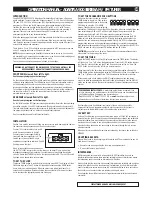
FRONT PANEL viewed from left to right.
See the upper photograph on the front page.
On the extreme left a stereo 6.35mm jack socket is provided to assist initial tuning and
setting up using headphones. The LED display is next. This gives information not only
on the frequency and channel in use but also on timer and clock settings. 14 non-
latching push buttons are then provided whose operation is described in detail below.
To the extreme right is the standby/on switch. Please note that whilst this switches off
the tuner, mains (and 12 volts when connected) are still present within the unit to
maintain the memory circuits.
REAR PANEL viewed from left to right.
See the lower photograph on the front page.
On the left is found the IEC input incorporating a mains fuse. Next is the chassis binding
post followed by the 12 volt DC input terminals. These are followed by the stereo left
(top) and right (bottom) phono output sockets with the Output Level control adjacent. At
the extreme right hand side will be found the Aerial Input terminals.
See the specification panel for full technical details.
INSTALLATION
Caution Care must be taken when fitting any connectors to avoid damaging the cable or
the connector through excessive heat from the soldering tool.
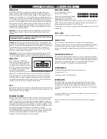
Connect 75
Ω
coaxial cable to terminals A
and B. Secure the cable with clamp C.
Connect screen (outer copper braid) to
terminal B and inner conductor to A. The
twisted pair of wires of the AM aerial
supplied are connected to terminals C and D
See diagram on the right.
When all connections have been made set
the OUTPUT LEVEL control at the rear to midway on its travel. Plug in a pair of low
impedance headphones for monitoring if no other means of monitoring is available
close by. Switch the STANDBY switch on the right-hand side to ON. The red LED should
light and a time should show in the window.
TO SET THE CLOCK
Toggle the TUNER button to read clock time only then press MEM. The display will then
flash showing a time. The UP button will then adjust minutes and the DOWN button
hours, both in an increasing mode. When the correct time is displayed leave for 5
seconds and the display will steady showing the corrected time. Care must be taken
not to overshoot the appropriate time when setting up.
TO SET THE PROGRAMME PUSH BUTTONS
Make sure the tuner is active by using the
TUNER button to toggle ‘on’. Then select a
programme button and tune in the desired
FM station by using the UP or DOWN
buttons. These buttons will auto-select the
next station if held down for longer than 500 milliseconds. When the desired station has
been selected press MEM and P1 will flash in the display. Then press and hold the
desired station selector M1to M8 for a few seconds to program the button. To
programme M9 to M16, when the desired station has been tuned in press the MEM
button twice in quick succession and P2 will flash in the display indicating that the
second of the two memories will be programmed. Press M9 to M16 to complete the
programming sequence. As the programme pushbuttons are selected the appropriate
push button number appears to the right of the display. The eight push buttons M1/9 to
M8/16 can each be set to two preset FM stations and one AM station.
THE TIMER
circuit should now be set up if required by the customer although this is
not essential for the working of the tuner.
TO SET THE TIMER
Toggle the TUNER button to the Clock Display and press the TIMER button. The display
will then show ‘T-on T-off’ above the displayed time. Press the M1/M9 button to select
the ‘Timer On’ state and then use the UP and Down buttons to set the ‘on’ time. The
M2/10 button is used to set the ‘off’ time in a similar manner.
Please note that for the timer to be active the tuner should be toggled off using the
TUNER button and the display toggled using the TIMER button to show the current time
and ‘T-on T-off’ above the current time. This then indicates that the timer is active.
Of the remaining two push buttons the MO/ST toggles between mono and stereo
output, the state being displayed in the top left hand of the display whilst the DISPLAY
button can be used to show the clock time instead of the tuner frequency and channel
number.
Most amplifiers have an additional level control of their which can be usefully
employed. Finally use a programme output to set the output level of the tuner in
conjunction with the amplifier control to fine balance the volume level.
12V BATTERY
Unless a 12 volt battery is connected all memories will be lost if the 240 volt supply is
removed from the tuner. Connect by using suitable spade lugs crimped and soldered to
the battery cables. Care must be taken to ensure that the terminals lie in the spaces
provided and do not swing to one side and thus short out on the mounting screws.
Polarity should be observed when connecting to the tuner although there is reverse
polarity protection.
When a battery is connected all memories are retained by the tuner when switched to
STANDBY.
MOUNTING BRACKETS.
These will be found in the packaging with the mains lead. The mounting holes can be
used in one of two ways:
• As ears for use when mounting the tuner into an equipment rack.
• To mount the tuner on top of a shelf.
INTERFERENCE
Whilst this equipment complies in all respects with EMC legislation its use in an
industrial environment where there are many potential sources of interference means
that steps may need to be taken to minimize any difficulties.
Always check that the tuner has a good aerial that is mounted externally and as high as
possible. An effective earth is also necessary if interference is to be minimised. In the
event of interference secure the services of a qualified electrician to carry out tests on
the socket in use to ensure that a low resistance earth path exists.
Do not position the amplifier very close to large transformers. television monitors and
computers.
OPERATION MANUAL - ADASTRA 900 SERIES AM / FM TUNER
GB
WARNING: DO NOT CONNECT THE MAINS SUPPLY TO THE TUNER UNTIL ALL THE
NECESSARYINPUT AND OUTPUT CONNECTIONS HAVE BEEN MADE.
PERFORMING RIGHTS LICENCE
- A performing rights licence is required if you
wish to play music to a public audience. In the UK this licence can be obtained from
the Performing Rights Society who can be contacted on:-
Tel:
08000 68 48 28,
Fax:
01733 312 912 or
email:
alternatively you can find more information at http://www.prs.co.uk
CIRCUIT DIAGRAMS ARE AVAILABLE ON REQUEST
A
B
C
D
FM 75
Ω
GND
AM


