background image


User Manual for ALPHA Director with Smart Alec option

Installation and setup: Updating the sign’s firmware (or EPROM)

 17


Updating the sign’s firmware (or EPROM)


From time to time it may be necessary to update the sign’s internal 

firmware by replacing an EPROM inside the sign. To do this, follow these 
steps:

1.

Remove power from the sign.

2.

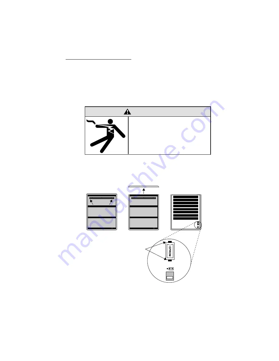
Replace the sign’s internal EPROM according to this diagram:

3.

Re-assemble the sign.

WARNING

Hazardous voltage. 
Contact with high voltage may
cause death or serious injury.
Always disconnect power 
to sign prior to servicing.

232

485

1.

Remove the two 
screws holding 
the signs’ cap.

2.

Remove the cap.

3.

Pull up and remove the clear 
plastic lens on the sign’s front.

Figure 4: How to change the sign’s EPROM

4.

To remove the current 
EPROM, grasp these two tabs 
and gently pull it out.

Then put in the new EPROM.

Summary of Contents for 0022-0001

Page 1: ...nual for ALPHA Director with Smart Alec option The ALPHA Director with Smart Alec option Display up to 26 pages of information 1997 Adaptive Micro Systems Form No 9705 1008 12 10 97 Assem bly instructions inside ...

Page 2: ...bol with each mention of the trademarked name the publisher states that it is using the names for editorial purposes and to the benefit of the trademark owner with no intention of improperly using the trademark BETA BRITE and BIG DOT are trademarks of Adaptive Micro Systems Inc registered in the United States Patent and Trademark Office ALPHA AlphaNET AlphaNET plus AlphaNET plus II ALPHAVISION Aut...

Page 3: ...all 4 How to mount the sign on a stand without the optional brochure rack 5 How to mount the sign on a stand with the optional brochure rack 9 Using the Remote Control 13 Connecting the sign to a computer 15 Updating the sign s firmware or EPROM 17 Basic sign operation 19 Turning a sign on and off 19 Setting a sign s serial address 20 ...

Page 4: ...daptive Micro Systems Inc any on site support service or maintenance Local ordinances prohibiting the use of flashing signs may exist in some locations Compliance with local ordinances is the sole responsibility of the customer To obtain warranty coverage this product must be registered Please complete the enclosed warranty registration card and mail it to Adaptive Micro Systems Inc How to obtain ...

Page 5: ...__________________ _____________________________________________ Return Instructions Step 1 Obtain an RMA number from your dealer distributor Step 2 Fill out this form and include proof of purchase receipt if product is under warranty Step 3 Pack this form the sign keyboard and transformer in the original carton or a suitable replacement Please write the RMA number on the outside of the package An...

Page 6: ...vi ...

Page 7: ...lay up to eight 16 character rows of text The sign can store up to 26 pages or screens of text information B Wall mounting bracket This is a factory installed option C RS232 RS485 jacks The bottom panel flips up to expose the RS232 RS485 jacks which are used to connect the sign to a computer or a network of signs See the manual Network Configurations 9708 8046 for more information on connecting th...

Page 8: ... manual may cause harmful interference to radio communications Operation of this equipment in a residential area is likely to cause harmful interference in which case the user will be required to correct the interference at his own expense Part number Description Input VAC Input power Dimensions in inches Weight in pounds 1022 1112 ALPHA Director with Smart Alec option 120 150 W 22 5L x 3 12D x 27...

Page 9: ...ause water and dust will damage the sign NOTE Because of its weight this sign should be assembled by two people WARNING Hazardous voltage Contact with high voltage may cause death or serious injury Always disconnect power to sign prior to servicing WARNING Fasten sign to floor Otherwise sign may tip over causing serious injury or death ...

Page 10: ...h another wall mounting bracket supplied to a wall Then hang the sign from this bracket NOTE Only hang the sign from a wall capable of supporting 116 pounds 52 5 kg 3 Route the power cord from the sign in such a way that the cord is not in an area where people will be walking Wall mounting bracket factory installed Attach a wall mounting bracket to a wall To mount the sign interlock the two bracke...

Page 11: ...he optional brochure rack 1 Remove the caps from the top of each mounting pole 2 Place both mounting poles on a flat surface Slide the crossbar down the channels on the mounting poles Then slide a safety stop down each channel Remove each end cap by unfastening the two screws that hold each cap Mounting poles Crossbar Safety stops ...

Page 12: ...the four set screws Then fasten each safety stop with the two set screws 25 5 inches 63 5 cm Fasten with two screws on each side Fasten each safety stop with two screws Crossbar Safety stop Mounting notch line up the bottom of the crossbar with this notch NOTE Screws should be securely tightened 18 to 20 inch pounds of torque recommended ...

Page 13: ...on Installation and setup Assembly 7 4 Place each of the sign s mounting brackets in a channel on each mounting pole Then slide the sign down until it rests on the safety stops Finally re attach the end caps onto the tops of the mounting poles End caps ...

Page 14: ...er cord from the sign in such a way that the cord is not in an area where people will be walking Top view of sign Completed assembly of sign Run the power cord along one of the mounting poles Use the supplied cable ties to fasten the power cord to the mounting pole Fasten the power cord to the floor in such a way e g tape to prevent someone from tripping over the cord Power cord Cable ties ...

Page 15: ... optional brochure rack 1 Remove the caps from the top of each mounting pole 2 Place both mounting poles on a flat surface Slide the crossbar down the channels on the mounting poles Then slide a safety stop down each channel Remove each end cap by unfastening the two screws that hold each cap Mounting poles Crossbar Safety stops ...

Page 16: ...r set screws Then fasten each safety stop with the two set screws 43 5 inches 110 5 cm Fasten the crossbar with two screws on each side Fasten each safety stop with two screws Crossbar Safety stop Mounting notch line up the bottom of the crossbar with this notch NOTE Screws should be securely tightened 18 to 20 inch pounds of torque recommended ...

Page 17: ...Assembly 11 4 Place each of the brochure rack s mounting brackets in a channel on each mounting pole Slide the brochure rack down until it rests on the safety stops Then slide the sign down the channels Finally re attach the end caps onto the tops of the mounting poles End caps ...

Page 18: ...le ties to fasten the power cord to the mounting pole Fasten the power cord to the floor in such a way e g tape to prevent someone from tripping over the cord Power cord Cable ties The plastic case can hold different sizes of literature Use the supplied plastic dividers to adjust for these sizes To remove the plastic case 1 Un screw the 4 screws from the crossbar 2 Slip the crossbar down 3 Loosen ...

Page 19: ... V W X M N P Q R O G H I J K L A B C D E F 1 2 3 4 5 6 7 8 9 0 AUTO SPEED TIME DOT ROLL WIPE SCROLL FLASH HOLD ROTATE APPEND CURSOR SPECIAL FONT WIDTH COLOR ON OFF REMOTE CONTROL SOUND INSERT BACK ADV DELETE PROGRAM RUN SELECT SPACE RETURN SHIFT CAPS SHIFT Figure 1 Infrared IR Remote Control keyboard Press PROGRAM to put the sign into programming mode This mode is used to change the sign s serial ...

Page 20: ...othing reflective is in front of the sign Light from the sign s display that is reflected back can interfere with the Remote Control If nearby fluorescent lights interfere with the Remote Control you may have to relocate either the lights or the sign If a sign is this far from the floor then hold a Remote Control this far away 10 feet from 10 to 30 feet 15 feet from 19 to 30 feet 20 feet from 25 t...

Page 21: ...ter If you only want to connect a single sign to your computer follow these steps 1 Remove power from the sign 2 Change the sign s internal RS232 RS485 jumper to RS232 according to this diagram WARNING Hazardous voltage Contact with high voltage may cause death or serious injury Always disconnect power to sign prior to servicing 232 485 1 Remove the two screws holding the signs cap 2 Remove the ca...

Page 22: ...85 jumper on page 15 Because there is such a wide variety of ways e g LAN wireless etc to connect signs see the manual Network Configurations 9708 8046 for more details Item Part Description A Ferrite ferrite end towards sign B 1088 8625 25 foot 6 conductor RS232 data cable 1088 8627 50 foot 6 conductor RS232 data cable C 4370 0001C 25 pin sub D to 6 pos RJ11 adapter 1088 9108 9 pin sub D to 6 pos...

Page 23: ...wer from the sign 2 Replace the sign s internal EPROM according to this diagram 3 Re assemble the sign WARNING Hazardous voltage Contact with high voltage may cause death or serious injury Always disconnect power to sign prior to servicing 232 485 1 Remove the two screws holding the signs cap 2 Remove the cap 3 Pull up and remove the clear plastic lens on the sign s front Figure 4 How to change th...

Page 24: ...User Manual for ALPHA Director with Smart Alec option 18 Installation and setup Updating the sign s firmware or EPROM ...

Page 25: ... press PROGRAM to turn a sign off and on NOTE Messages that you have programmed into the sign will not be lost when you turn a sign off Messages will be retained for up to 30 days if the sign is not powered When you turn a sign on information similar to the following will be displayed 1022 6801A 16X8C SMART 64K RAM TUESDAY 3 12 PM APRIL 15 1997 SERIAL ADDRESS 000 Model number of the sign Total amo...

Page 26: ...ess to a sign allows you to send messages to that particular sign See the document Network Configurations part number 9708 8046 for more detailed information on networking signs Step When you do this You see this 1 Press PROGRAM 1 Press ADV 4 Type a number like 010 NOTE A serial address is a number from 0 to 255 NOTE When a sign leaves the factory its serial address is set to 000 5 Press RUN once ...

Reviews: