background image

Adamczewski GmbH

Manual AD-MM 500 FE

5 Assembly and commissioning

Electrical connection

The terminals of the auxiliary voltage inputs are dangerous to touch

.

Disconnect the mains voltage and secure it against reconnection.

Ensure that the connections are protected against accidental contact.

Protect all connections against electrostatic discharge.

Commission the appliance

Switch off the power supply.

Check that there is no voltage.

Mount the unit.

Connect power supply and RS-485.

Switch on power.

Configure the unit. See chapter 6 for details.

Check function.

10 / 36

1.0 2021-05-19

Summary of Contents for AD-MM 500 FE

Page 1: ...Display device control unit and data logger AD MM 500 FE Manual Version 1 0 2021 05 19 ...

Page 2: ... Network interface 9 4 9 USB Interface 9 4 10 Display 9 4 11 Operation 9 5 Assembly and commissioning 10 6 Operation and menu navigation 11 6 1 Key functions 11 6 2 Normal operation 12 6 3 Scroll display 13 6 4 Main menu 14 6 4 1 Select slave and function 14 6 4 2 Options 17 6 4 3 Info 17 6 4 4 Backup to USB 17 7 Configuration 18 7 1 Logging 18 7 2 Displays 21 7 3 Display elements 22 7 4 Channels ...

Page 3: ...bsequent owner or user of the product Structure of the warnings Please consider the documentation This symbol is intended to warn you of possible hazards that could arise during assembly commissioning and use Here actions to avoid the danger are available Structure of the hazard warnings Danger to life or serious injury Disconnect the system and the unit from the power supply before starting work ...

Page 4: ...GmbH is not liable for any damage resulting from this or for damage or for damage resulting from improper use Malfunctions that may impair safety must be eliminated immediately The installer must make the manual available to the operator The installer and the operator must have read and understood the manual before starting their work Foreseeable misuse In particular this product must not be used ...

Page 5: ...nd are prohibited for safety reasons Use of spare parts and accessories The use of unsuitable spare parts and accessories can damage the product Please use only original spare parts and accessories from the manufacturer Disclaimer The manufacturer accepts no liability or warranty for damage or consequential damage resulting from failure to comply with the technical regulations instructions and rec...

Page 6: ...ted or changed by the customer the USB adapter VarioPass available from the manufacturer is required Features Display unit operating unit and data logger for front panel installation Display via graphic capable TFT display RS 485 interface with Modbus RTU protocol Interface for configuration or firmware update Creation of own displays with the Configuration program AD Studio Up to 10 configurable ...

Page 7: ...date of the AD MM 500 FE Display and operating elements The AD MM 500 FE has a colour graphics capable TFT display for showing the data and three buttons for operation and configuration TFT Display Up Set Down Figure 3 1 Display and operating elements of the AD MM 500 FE key Up Scroll up increment digit key Down Scroll down decrement digit key Set Confirm input 7 36 1 0 2021 05 19 ...

Page 8: ... Protection class terminals IP 20 Connection technology removable screw terminals Construction panel housing Weight 350 g 4 3 Environmental conditions Name Value Ambient temperature 0 50 C Storage and transport 10 70 C avoid condensation Degree of contamination 2 4 4 EMC Name Value Product family standard EN 61326 Emitted interference EN 55011 CISPR11 Class B 4 5 Electrical safety Name Value Produ...

Page 9: ...guration interface Name Value Connector jack socket 3mm Standard UART manufacturer specific Function Configuration 4 8 Network interface Name Value Connector RJ45 socket Standard Ethernet Function reserve for later extensions 4 9 USB Interface Name Value Connector socket type A for USB stick Standard USB 1 0 2 0 Function data transfer 4 10 Display Name Value Type 3 5 TFT Resolution 320x240 Pixel 4...

Page 10: ...and secure it against reconnection Ensure that the connections are protected against accidental contact Protect all connections against electrostatic discharge Commission the appliance Switch off the power supply Check that there is no voltage Mount the unit Connect power supply and RS 485 Switch on power Configure the unit See chapter 6 for details Check function 10 36 1 0 2021 05 19 ...

Page 11: ...owing abbreviations apply to the key functions up Press the Up key briefly UP Press the Up key for longer than approx 3 sec down Press Down key briefly DOWN Press the Down key for longer than approx 3s set Press the Set button briefly SET Press the Set key for longer than approx 3s NO key combinations are used in the entire menu one finger menu 11 36 1 0 2021 05 19 ...

Page 12: ...isplayed with up or down or automatically In the Main menu see chapter 6 4 among other things Settings can be made on the AD MM 500 FE the logged data is saved on a USB stick Settings of a slave can be made via its slave menu The simulation of an input of a slave can be executed Since the AD MM 500 FE often accesses the connected slaves to display the data as well as in the main menu there is a hi...

Page 13: ... 6 2 Scrolling the displays of the AD MM 500 FE manually or automatically The displays can be scrolled up and down either manually with the Up and Down keys as shown in the image 6 2 or automatically time controlled When starting you can first scroll through Scroll manual with up and down With UP or DOWN you branch to Scroll automatic where after a corresponding interval you automatically scroll u...

Page 14: ...of the AD MM 500 FE The main menu is used to access a slave on the one hand and to make settings on the AD MM 500 FE or perform device functions on the other Settings for the AD MM 500 FE can be made under Options 6 4 1 Select slave and function In order to work with the slave you must first set the slave address under Select slave The default value is 1 Then under Select function you can choose w...

Page 15: ...der Select slave and then under Select function the slave menu The AD MM 500 FE now fetches all the data it needs to display the menu from the slave The image 6 4 shows how to navigate in the slave menu edit parameters and execute device functions The content of the slave menu depends on the device type of the slave The way the menu is displayed and operated however is always the same since these ...

Page 16: ...00 FE now fetches the available simulation channels from the slave and displays them in the Select simulation channel menu Only one simulation channel can be selected and edited at a time If a slave offers several simulation channels all other channels will continue to be recorded as analog inputs After selecting the desired channel you get to Manual simulation The display is the same as in normal...

Page 17: ... FE and also of the slave are not or only partially accessible Language The menu language for the AD MM 500 FE and also the slave menu can be selected here Brightness The brightness of the TFT backlight can be set in here Drag pointers All drag pointers can be reset here Note A drag pointer runs in the back ground for each channel regardless of whether it is displayed or not Date The date for the ...

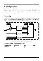
Page 18: ...condition or conditionally Conditional logging can be controlled by a limit value a trend or by a time condition It also checks the availability of the hardware Grenzwert Trigger Trend Trigger Zeit Trigger Hardwarestatus RTC EEPROM SD Karte Hysterese Fenster Trend steigend Trend fallend Trend gleich Intervall einmalig Intervall täglich Startzeit dauernd Zeitstempel Log Modus Triggerkanal Kanal 1 K...

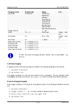
Page 19: ...1 2018 11 11 12 To start and stop the logging process quickly use the parameter Log Release Continuous logging If logging is to be continuous and without condition the following parameters must be set 1 Log mode Continuous 2 Log enable Yes The trigger conditions for limit trend and time are not considered The log operation starts immediately and does not end until Log enable No is set or another l...

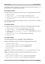
Page 20: ...creasing or Trend equal 2 trigger channel 1 32 Channel number for determining the value 3 trend delta Signal difference to be supervised Signal difference from which a trend is detected 4 Trend Time Time Interval Time interval between measurements 5 Log enable Yes Time triggered logging Time triggered logging can be done once daily or from a certain time on If once is to be logged at a certain tim...

Page 21: ...o be logged the following parameters must be set 1 Log mode Start time continuous 2 Start time continuous DD MM YYY hh mm ss Start date and time 3 Log enable Yes Logging takes place if the current time is after the start time 7 2 Displays The AD MM 500 FE can show up to 10 displays These can be scrolled through either manually with the up and down keys or automatically with a timer A display can s...

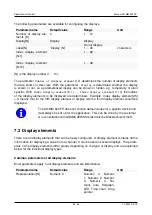
Page 22: ...ement 2 5 3 means that for the fifth display element of display two the third display element should be displayed The AD MM 500 FE does not contain default values for a specific device and must always be set up for the application This can be done by the customer or in consultation with ADAMCZEWSKI elektronische Messtechnik GmbH 7 3 Display elements There are 40 display elements that can be freely...

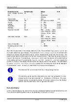
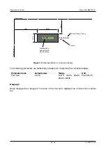
Page 23: ...the color change function They have the same unit as the value of the channel The parameter Labelposition N sets the position of the label relative to the display element The parameters Top N Left N Height N Width N specify the position and size of the display element within the display area of the display The parameters Standard color N Alternate color N specify the colors how the value will be d...

Page 24: ...Höhe Oben Figure 7 3 Representation as numerical display The following parameters are additionally available for configuring the numerical display Parametername Default value Range Unit Font size 13x13 13x13 19x16 32x32 35x45 46x60 Pixel WxH Bargraph When displayed as a bargraph the value of the channel is displayed as a horizontal or vertical bar 24 36 1 0 2021 05 19 ...

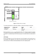
Page 25: ...tal Horizontal Vertical With the parameter Scaling range the physical value of the channel is scaled to the position and the size of the bar within the display area The Orientation parameter sets the orientation of the bar For Horizontal the bar runs from left to right for Vertical the bar runs from bottom to top LED Display With the LED display the color of the active area of the LED changes from...

Page 26: ...ly e g green active gray not active The diameter of the LED is specified in the parameter Width Timing diagram display With the time diagram display the current value of the channel is plotted over the time axis over a defined period of time After each sampling interval a new value is calculated and plotted over the time axis The time span that can be plotted over the time axis is calculated as td...

Page 27: ...e minimum and maximum values are always determined automatically from all channels that are queried 7 4 Channels There are 32 channels that can be freely configured The channels save all parameters that the AD MM 500 FE needs to acquire a value via Modbus The following parameters can be configured for each channel Parametername Default value Range Unit Slave address N 1 1 247 Holdingregister N 0 6...

Page 28: ...With this settings the AD MM 500 FE fetches every 10s a floating point value from modbus slave 2 at address 41120 Floating point numbers single or float according to IEEE 754 are 4 bytes so 2 Modbus registers are read 28 36 1 0 2021 05 19 ...

Page 29: ...its 1 Data types The following data types are used Type Size Words bool 1 Byte 1 u16 2 Byte 1 u32 4 Byte 2 single IEEE 754 4 Byte 2 According to the Modbus specification words with two bytes are transmitted as the smallest unit in the Big Endian format All information is therefore a multiple of a word The checksum is an exception It is sent in the little endian format least significant byte first ...

Page 30: ...CH 1 0x03 0x9F 0x61 0x00 0x02 Response SA FC BC D0H D0L DNH DNL CRCL CRCH 1 0x03 4 0x00 0x00 0x00 0x00 In the event of an error the slave responds with an error message Exception Slave Errorcode Exception CRC Low CRC High 1 0x83 see 8 Write Multiple Registers This function is used to write one or more registers The master sends a request with the start address the number of registers and the regis...

Page 31: ... Exception Slave Fehlercode Exception CRC Low CRC High 1 0x90 siehe 8 Exception Codes If the request is incorrect the slave responds with a Error telegram and one of the following exception codes As Error code the function code is sent back ORed with 0x80 1 0x01 The Modbus function is not supported 2 0x02 The register address does not exist 3 0x03 The data is invalid 31 36 1 0 2021 05 19 ...

Page 32: ...pin Function M101 1 L DC M101 2 N DC M301 Ethernet Reserve M202 1 RS 485 A M202 2 RS 485 B M202 3 RS 485 Ground M203 3mm Jack for Variopass M201 USB socket type A for USB stick M202 PCB1 M301 M203 M201 1 2 3 1 2 Figure 9 1 Pin assignment of the AD MM 500 FE Rear view 32 36 1 0 2021 05 19 ...

Page 33: ...dbus over serial line Figure 9 2 RS 485 with several bus participants ITr Twisted shielded cable must be used as a bus cable IDv Passive stub lines must be as short as possible Mass The earth connection of all bus participants must be connected to one another LT The bus line must be terminated at both ends with terminating resistors of 120 Ohm between lines A and B 33 36 1 0 2021 05 19 ...

Page 34: ...by the manufacturer Disruptions If an error or a malfunction occurs first try to find the cause If the error persists please contact the manufacturer or dealer of the device you can find in chapter 10 Storage management and data formats of the files on the SD card The figure 10 1 shows an example of the file system on the SD card as it is also transferred to a USB stick during a backup The name of...

Page 35: ... Configuration program AD Studio data line 11 11 2011 11 11 11 1 2345 2 3456 Channels that are not logged remain empty Storage requirement of the data on the SD card The required memory on the SD card essentially depends on the number of channels and the log interval The internal SD card has a standard 2GB storage capacity The table shows the storage requirements in GB per year for a specific appl...

Page 36: ...35 0 39 0 56 0 73 0 89 1 06 1 23 1 40 1 57 8 0 23 0 27 0 30 0 34 0 49 0 64 0 78 0 93 1 08 1 22 1 37 9 0 21 0 24 0 27 0 30 0 43 0 56 0 70 0 83 0 96 1 09 1 22 10 0 19 0 21 0 24 0 27 0 39 0 51 0 63 0 74 0 86 0 98 1 10 20 0 09 0 11 0 12 0 14 0 20 0 25 0 31 0 37 0 43 0 49 0 55 30 0 06 0 07 0 08 0 09 0 13 0 17 0 21 0 25 0 29 0 33 0 37 40 0 05 0 05 0 06 0 07 0 10 0 13 0 16 0 19 0 22 0 24 0 27 50 0 04 0 0...

Reviews: