


4 of 5
G
!
C
ONFIGURATION
D
ETAILS
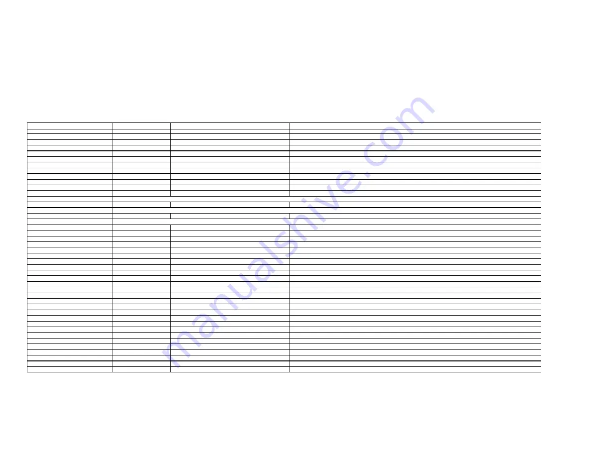
The following table provides settings used in the g! Configurator. Please refer to the
g! Configurator Reference Guide
for more details.
o
“<Select>”
Select the appropriate item from the list (or drop-down) in the Configurator.
o
“<User Defined>”, etc.
Type in the desired name for the item.
Devices
Variable Name
Setting
Comments
Communication Devices
Name
<User Defined> (Default:
Receiver
)
Type
Serial Port
Refer to the RS-232 Connection Option Integration note for alternative configurations
Communication Type
<Select>
Select the Communication Type that matches your receiver, if no comapatible type is listed then select Standard Connection
Location
<User Defined> (Not Required)
COM Port
<Select>
Audio Tuners (Optional)
Name
<User Defined> (Default:
AM/FM Tuner
)
Optional: Only needed if the tuner will be a visible source in the Viewer interface
Device Type
<Select>
Select the tuner that matches your receiver
Location
<User Defined> (Not Required)
COM Device
<Select> (Default:
Receiver
)
<Other RS-232 Sources>
<Other IR Controlled Sources>
<Video Display>
Add the Video Display for the receiver. Refer to the Integration Note for the specific display, or the
Generic Video Display
Integration Note for an IR controlled display
Other Audio Devices / Interfaces
Name
<User Defined>
Add one Interface for each source that should appear in the Viewer
Template
<Select>
Default Device
<Select>
Select the RS-232 or IR controlled source for this interface
Audio Zone Controllers
Name
<User Defined>
Defaults to the make and model of your receiver, after selecting Device Type
Device Type
<Select>
Select your model of receiver
Location
<User Defined> (Not Required)
COM Device
<Select> (Default:
Receiver
)
Sources
Name
<User Defined>
Source Device
<Select>
Sources must be previously configured in order to allow selection.
Source Icon
<Select>
This icon appears on the source button in the Viewer Interface
Display Name
<User Defined>
This text appears on the source button in the Viewer Interface
Zones
Name
<User Defined>
Display
<Select>
Select the Video Display in this zone
Universal Receiver
<Select>
Refer to the HomeLogic Universal Remote Integration Note for more details
<Source>
Display On/Off
<Select>
For each source, select what the display should do when that source is active
Display Source
<Select>
If using more than one input on the video display select the input for each source.
Show Source
<Select>
Set to
No
for any inputs on the receiver that are not used or do not want to be seen in the zone
<Interface Tab>
Click on the Interface tab in order to hide or show zone tabs on indivdual touchscreens
<Touchscreen Options>
Select the touchscreen to modify from the list
Tab Layouts
<Select>
Move any unused zone tabs into
Available Zones
to remove from the viewer
Add any other RS-232 controlled sources. Refer to the Integration Note for each specific source device.
Add IR devices on the Input/Output tab for other IR controlled sources. Refer to the
Generic IR Source
Integration note.
Summary of Contents for Suite 7.1
Page 5: ...5 of 5 COMMON MISTAKES ...


