background image

100S

Reference Manual

24

OPERATION

6. Press the 

Y

key. Enter the bolthole pattern’s center point on the Y-axis. 

Use a decimal point and minus (-) sign if necessary. 

7. Press the 

ENTER

key.

8. Press the 

ENTER

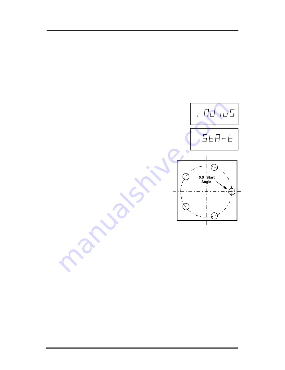
key again. “Radius” will appear. 

9. Enter the radius of the circle pattern. Press 

ENTER

.

10. Press 

ENTER

again. "START" will appear on 

the X-axis display.

11. Enter the start angle of the first hole in 

the bolthole pattern. (0 degrees is at the
3 o’clock position.) Use a decimal 
point and minus (-) sign if necessary. 

12. Press 

ENTER

to complete the pattern. 

Summary of Contents for 100S

Page 1: ...100S READOUTS FOR MILLING APPLICATIONS REFERENCE MANUAL SALES SERVICE A Tech Authority Inc 13745 Stockton Ave Chino CA 91710 909 614 4522 sales atechauthority com ...

Page 2: ...pensation 7 How to Determine the Linear Error Compensation 8 Scale Resolution 9 Count Direction 10 Position Recall 10 Testing the Scales 11 Counting Test 11 Repeatability Test 11 Power On Position Recovery 12 Position Recall 12 Reference Mark Evaluation 12 Setting the Datum Absolute Zero 13 At Current Position 14 Using an Offset 14 Example Absolute Dimensions 15 100S Reference Manual i TABLE OF CO...

Page 3: ...tum on a Centerline 20 Example Setting the Datum on a Centerline 21 Locating Centerline Using Incremental Dimensions 22 Bolthole Patterns 23 Creating a Bolthole Pattern 23 24 Running a Bolthole Pattern 25 Troubleshooting Reference Introduction 26 Error Messages General 31 Error Messages Keypad Test 32 Electrical Specifications 33 Factory Default Settings 34 Keypad 35 36 Conventions 37 Count Direct...

Page 4: ...ion of the 100S system Use it to get your system up and running out of the box and as a quick reference guide for your day to day opera tions Here s how a typical machine will look after the installation is com plete Mounting Arm 100S Readout Z axis Scale if applicable Y axis Scale X axis Scale behind the table ...

Page 5: ...e back of the display the scale s catalog number is on the scale assembly label and the serial number is on the scale case Copy the information here for your own records and mail the warranty card as soon as possible Preparation Distributor _____________________________________________ Address _____________________________________________ Telephone _____________________________________________ Cat...

Page 6: ...n instructions that are included with your mounting arm bracket kit The electrical specifications for the readout are listed on pg 33 After the installation is complete proceed to Power Up Installing the Scales Please see the manual included with the scale for installation instructions ...

Page 7: ... It merely indicates that the system had lost power To acknowledge the message press the CLEAR key and proceed to the DRO mode Note If the E1 message appears at any other time during normal operation refer to pg 31 for possible problems and solutions When the system is not used for more than 90 minutes a decimal point will scroll across the display indicating that the display saver has been activa...

Page 8: ...n change the parameters later by returning to Setup and then using the ENTER key to scroll to the appropriate category Anytime you change the linear error compensation or count direction for an axis the absolute and incremental displays for that axis will be reset to 0 If you change these settings you will need to re establish the datum point When in the Setup mode use the CLEAR key when you want ...

Page 9: ...on the display Press the X Y or Z key for the display you want to change For 10µm scales the display resolution will toggle between 0 01 mm 0 0005 and 0 02 mm 0 001 For 5µm scales it will toggle between 0 005 mm 0 0002 and 0 01 mm 0 0005 For 1µm scales it will toggle between 0 001 mm 0 00005 and 0 002 mm 0 0001 After you complete setting your display resolution press ENTER to continue with setup o...

Page 10: ... Setup mode Press SETUP and then the ENTER key until the display appears Press the X Y or Z key for the axis you want to change 100S will display the current LEC value for that axis Using the keypad enter the linear error compensation factor in PPM followed by a or sign The number must be within 9999 and 9999 use whole numbers The formula for calculating the value is on the next page After you com...

Page 11: ...l indicator reaches the opposite end of the standard Write down the length that is shown on the readout display for that axis Use the formula below to calculate the LEC for the axis you just measured Enter the result in the LEC screen previous page Note If the measured length is greater than the standard length the LEC value will be negative How to Determine the Linear Error Compensation Follow th...

Page 12: ... necessary choose Scale Resolution from the Setup menu Press SETUP and then the ENTER key until the screen appears Press the appropriate axis key until the appropriate resolution appears Choose 0 01 mm for 10µm 0 0005 scales 0 005 mm for 5µm 0 0002 and 0 001 mm for 1µm 0 00005 scales Repeat the procedure for each axis Press ENTER to continue with Setup To change the scale resolution ...

Page 13: ...l DRO display To change the count direction Count Direction Use the count direction setting to define the positive counting direction for each scale The direction will be displayed as a 1 or a 2 the numbers are not assigned to a particular direction You only need to change the count direction if the scale is counting in the negative direction during a positive table move or vice versa Refer to Con...

Page 14: ... s movement If it doesn t then the scale resolution you selected may not be accurate Refer to Scale Resolution pg 9 Repeatability Test Locate a magnetic base and dial indicator on the end of the scale Zero the readout and the indicator Move the axis through the full travel and return the dial to 0 The readout should also read 0 0 0005 for 10µm scales 0 0002 for 5µm scales 0 00005 for 1µm scales If...

Page 15: ...datums To perform Reference Mark Evaluation Move near the appropriate reference mark Press and hold the DECIMAL key until the decimal points on the displays start to flash Move slowly past the reference mark until the readout recalls its position Repeat for each axis Power On Position Recovery With the 100S there are two means of position recovery Position Recall and Reference Mark Evaluation Posi...

Page 16: ... reference point from which 100S will base all of your part s coordinates When the readout is in the ABS mode it is actually measuring the distance from the datum to the table s current position You will need to establish a datum for every job Your datum may already be identified on your print if it isn t then establish a datum that allows you to enter most of your part s dimensions directly with ...

Page 17: ...he point you want to establish as the datum Include a decimal point and minus sign when necessary Press the ZERO key for another axis or press ENTER to return to the DRO display To set the datum using an offset To set the datum at the tool s current position Position the workpiece on the table Move the table until the tool is centered on the edge of the workpiece at the location where you would li...

Page 18: ...he ABS INCR key if necessary By selecting ABS you re telling 100S to measure the machine s movement on the X Y and Z axes from your datum 0 0 0 Press the MM key until Inches is selected the MM LED is not lit up For Hole 1 move the table until X 2 00 and Y 1 5 Drill Hole 1 Move the table until X 4 00 and Y 1 5 Drill Hole 2 Move the table until X 6 00 and Y 1 5 Drill Hole 3 Let s say that your print...

Page 19: ...you want to measure an incremental distance from Using the ABS INCR key select the incremental INCR mode on the readout Also check that the proper measurement inch or mm is selected Press the ZERO key below the axis es from which you are measur ing Move the table 100S will display the table s position in relation to the 0 point s for the axis es you chose After you have reached the position you wa...

Page 20: ...ny calculations 1 Press the ABS INCR key until ABS is selected on the DRO display Press the MM key until Inches is selected the MM display is not lit up 2 For Hole 1 move the table until X 2 00 and Y 1 5 Drill Hole 1 3 Now press the ABS INCR key so that INCR is selected on the DRO display This tells 100S that you want to measure the distance from the current position to the next point 4 Press the ...

Page 21: ...incremental distance you want to move or the end point of an absolute dimension first and then count down to 0 For instance if you enter 3 125 as an incremental dimension preset distance 100S will show 3 125 on the display As you move the table in the positive count direction the system will start counting When the axis display reads 0 your tool is in the correct position Using Incremental Presets...

Page 22: ...ow press the ABS INCR key so that INCR is selected on the DRO display 4 Press the X key and ensure the INCR led is lit Enter 2 as the incremental distance from Hole 1 to Hole 2 and then press ENTER Two inches is the incremental preset distance 5 Move the table until X 0 000 and Y 0 000 Drill Hole 2 6 Press the X key and ensure the ABS led is lit by pressing the ABS INCR key Then enter the ABS dime...

Page 23: ...ntil ABS is selected 2 Move the table to the first location 3 Press the ZERO key twice for the axis X Y or Z you want to find the centerline 4 Move the table to the second location along the same axis 5 Press the C L centerline key Dashes will flash on the screen 6 Press the appropriate key X Y or Z for the axis you re measuring 7 100S will measure the distance between the two points then divide t...

Page 24: ...tween the two points The display will show the distance from the current position to the centerline 5 Move the table until the indicator rests against the other side of the circle Press the C L centerline key Press the Y key and MICRO LINE will calculate the centerline and display the distance from the current position to the centerline Your datum is now located at the center of the circle 4 Now f...

Page 25: ...will zero the current position 4 Move the table to the second location along the same axis 5 Press the C L centerline key Dashes will flash on the screen 6 Press the appropriate key X Y or Z for the axis you re measuring 7 100S will measure the distance between the two points then divide the sum in half You can locate the centerline by moving the table until the position for the axis you measured ...

Page 26: ... number of holes up to 99 center point radius and start angle 100S will automatically position Hole 1 at the start angle and space the holes equally throughout the pattern To create a bolthole pattern Bolthole Patterns 1 Press the BOLT DEF key HOLES will appear on the X axis display 2 Enter the number of holes 1 99 in the pattern Press the ENTER key 3 Press the ENTER key again Center will appear a...

Page 27: ...the ENTER key 8 Press the ENTER key again Radius will appear 9 Enter the radius of the circle pattern Press ENTER 10 Press ENTER again START will appear on the X axis display 11 Enter the start angle of the first hole in the bolthole pattern 0 degrees is at the 3 o clock position Use a decimal point and minus sign if necessary 12 Press ENTER to complete the pattern ...

Page 28: ... and Hole 2 will appear Move the table to 0 drill the hole and continue with the rest of the pattern If you want to start at a differ ent place in the pattern press BOLT USE followed by the number of the hole you want to begin with Notice that the system automatically switches to the incremental mode whenever you run a pattern That s because the system is using incre mental presets pg 18 to measur...

Page 29: ...se and Recommended Corrective Action The symptoms are listed in the order of the most common easiest to check and least expensive to correct First locate the symptom that best describes the problem you are trying to solve Then identify the probable cause that most closely matches the problem and implement the recommended corrective action If a problem persists or cannot be resolved using this manu...

Page 30: ...back of the console is on No power to the readout Check that the readout s power cord is properly connected to the power supply Check that the power source meets the specifica tions required by your system pg 33 Contact your 100S distrib utor for repair replacement procedures LED failure Dashes appear on screen The value entered exceeds the display s 8 character capability Enter a value with less ...

Page 31: ...error messages Dashes appear on screen cont d Move the table toward the 0 position As the scale counts down the display will show the correct position Display overflow Turn the system off and then on again using the switch on the back of the readout If an error besides E1 is still detect ed when the system is powered up contact your 100S distributor for repair replacement proce dures Refer to pg 3...

Page 32: ... scale instal lation instructions Scale not installed properly Scale won t count Check the scale and reading head for proper installation refer to scale installation instructions included with your system Clean the scale if necessary Scale not installed properly Change the count direction pg 10 Wrong count direction Symptom Recommended Corrective Action Probable Cause Unplug the scale from the rea...

Page 33: ...ill not be saved Refer to pgs 5 11 for proper procedures Setup does not save values Numbers don t appear are faded on the display LED failure Turn the system off and then on again using the switch on the back of the readout If this does not correct the problem contact your 100S distrib utor for repair replacement procedures Symptom Recommended Corrective Action Probable Cause ...

Page 34: ...the system does not operate properly contact your 100S distributor for repair replacement procedures A scale miscount error invalid waveform error has occurred The E9 message will appear on the axis that has the error Press CLEAR to reset the axis es Your current position may be lost Re establish the datum if necessary If the system does not operate properly con tact your 100S distributor for repa...

Page 35: ...clear the error message If the key does not work during normal operation contact your distributor for repair replacement procedures SETUP key E11 E12 MM key E15 E16 X key E18 E21 BOLT DEF key E22 E25 7 key E26 E28 C L key ABS INCR key 9 key 8 key ZERO key for the X axis E31 6 key E35 E36 E38 E41 E45 E46 E48 E51 E54 E55 E32 E56 BOLT USE key 5 key 4 key 1 Axis X key 2 3 Axis Y key E33 CLEAR key 3 ke...

Page 36: ...ationship Maximum input rate 70 kHz Encoder input This device complies with Part 15 of the FCC Rules Operation is subject to the following two conditions 1 this device may not cause harmful interference and 2 this device must accept any interference received including interference that may cause undesired opera tion Size 9 875 x 4 679 x 4 75 Electrical Specifications Weight 4 lbs 2 oz Mounting Bot...

Page 37: ...Linear Error Compensation Scale Resolution Count Direction Bolt Circle Display Units Display Mode 0 0005 0 01 mm for 10µm scale 0 parts per million 0 0005 0 01 mm 10µm 1 1 Number of Holes Center Radius Start Angle 0 0 0 degrees 0 Inches ABS absolute dimensions Position Recall Off ...

Page 38: ...C L CENTERLINE Locates the centerline of the workpiece pg 20 MM Press this key to switch X Y Z displays between English and metric units X Y Z ZERO Correspond with the scales on the X Y and Z axes Used to specify a change to a particular axis These keys reset the incremental or absolute display position at 0 for the corresponding axis SETUP Provides access to the display resolution linear error co...

Page 39: ... create a bolthole pattern Used to run a bolthole pattern Acts as backspace key during numeric entry otherwise it clears or cancels the last operation ENTER Completes numeric operations selects next parameter in SETUP or BOLT DEF operations Decimal point can be used during numeric entry This is also used to initiate a reference mark evaluation 0 9 Used to enter a distance angle or other number val...

Page 40: ...l All of the examples in this manual are based upon this setup X axis The table will move to the left and the tool will move to the right for a posi tive count direction Y axis The table will move toward you while the tool moves away from you for a positive count direction Z axis The quill will move up away from the table surface for a positive count direction Count Direction Conventions This sect...

Page 41: ...tion caused in whole or part by the customer s incorrect use improper maintenance modifica tion of the equipment or by the repair or maintenance of the product by any person except those deemed qualified by ACU RITE Responsibility for loss of operation or diminished performance due to conditions beyond ACU RITE s control cannot be accepted by ACU RITE The foregoing warranty obligations are in lieu...

Page 42: ...DUSTRIAL PARK JAMESTOWN NY 14701 www acu rite com 532821 20 ACU RITE Readout Systems are manufactured in the USA ACU RITE IS AN ISO 9001 CERTIFIED MANUFACTURER SALES SERVICE A Tech Authority Inc 13745 Stockton Ave Chino CA 91710 909 614 4522 sales atechauthority com ...

Reviews: