


6
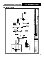
Installation and Commissioning Guide
Mini Cassette Split System
Installation and Commissioning Guide - Mini Cassette 2 Split System
Doc. No. 9590-5010
Ver. 1 211217
Service Equipment and Recovery Procedures
Always use refrigerant reclaiming equipment in order to minimise refrigerant emissions. Use equipment and methods
which will pull the lowest possible system vacuum while recovering and condensing refrigerant. Equipment capable of
pulling a vacuum of less than 500 microns is required.
Do not open the system to the atmosphere for service work until refrigerant is fully removed and/or recovered. Perform
refrigeration system evacuation, prior to charging, in accordance with AIRAH / IRHACE Refrigerant handling code of
practice.
Let the unit stand for 1 hour and with the vacuum not rising above 500 microns. A rise above 500 microns indicates a leak
from the system and a leak test is required to locate and repair any leak.
Charge refrigerant into the system only after the equipment does not leak or contain moisture. Take into consideration
the correct amount of refrigerant charge specified for the system to ensure efficient unit operations. When charging
is complete, reclaim refrigerant from charging lines into an approved refrigerant container. Seal all used refrigerant
containers with approved closure devices to prevent unused refrigerant from escaping to the atmosphere. Take extra
care to maintain all service equipment directly supporting refrigerant service work such as gauges, hoses, vacuum pumps
and recycling equipment.
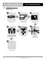
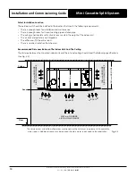
INSTALLATION PREPARATION (Pre-Installation considerations)
The following items must be considered before beginning the unit installation:
•
Verify the unit capacities and ratings with the unit nameplate.
•
Make certain the floor or foundation is level, solid and has sufficient structural strength to support the unit and
accessories weight.
•
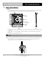
Install anti-vibration rubber (installer to supply) under
all of the unit’s feet
to help reduce noise and minimize
vibration transfer through the foundation. Ensure that all anti-vibration rubbers are rated to provide stable support
without impairing the unit’s structural integrity.
•
Diameter or width of anti-vibration rubber’s must be at least equal to the width of the actual feet to prevent
deformation overtime.
•
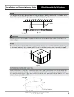
Allow minimum recommended clearances for periodic maintenance and service access.
•
Allow sufficient space beside the unit for the outdoor air discharge. Condenser air inlet, located on the coil side of the
unit, requires sufficient airflow clearance for the optimum unit performance.
•
Note the conditioned supply air and return air location. Ensure sufficient spaces are allocated for these purposes.
•
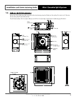
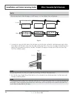
For the connection and location of condensate drain in the unit, refer to the drawings and dimensions section of this
manual.
•
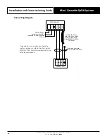
Wiring connections must be in accordance with the wiring diagram provided with the unit.
•
Make sure all wirings are in accordance with local electricity authority regulations and standards.
•
Do not install the unit close to an area where there is a danger of fire due to volatile, explosive, flammable and/ or
hazardous materials.
•
Ensure that spaces around the unit are free from any obstructions for optimum unit performance.
•
Installer to ensure correct size/type that main circuit breaker and cable is installed in unit sub-mains to protect the
sub-mains and unit wiring.
•
Installer to ensure correctly rated residual current device (RCD) is installed as per the latest version of the AS/NZS
3000 (also known as Australian Wiring Rules).
CAUTION
This indoor unit is designed to match only with the ActronAir outdoor unit as specified in the Technical Selection Catalogue.
The unit is supplied with factory charged R-32 refrigerant and is designed for use with R-32 refrigerant only.
Be aware of all the relevant regulations concerning the handling of refrigerant.
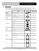
Optional accessories
There are two types of controlers: wired and wireless. Select a remote controller based on customer preferences and
requirements and install in an appropriate place.
Refer to catalogues and technical literature for guidance on selecting a suitable remote controller


