background image

2K 200

20M

2M

200K

20K

OHMS

750V AC
200V DC

COM

V

DWELL

CYL

CYL

CYL

CYL

9

5. Connect RED and BLACK test leads

across component where you want to

measure resistance.

When making resistance measurements,

polarity is not important. The test leads

just have to be connected across the

component.

6. Turn multimeter rotary switch to

desired OHM range.

If the approximate resistance is unknown,

start at the largest OHM range and

decrease to the appropriate range as

required. (See Setting the Range on page 6)

7. View reading on display - Note range

setting for correct units.

NOTE:  2K

 = 2,000

; 2M

 = 2,000,000

If you want to make precise resistance

measurements, then subtract the test

lead resistance found in Step 4 above

from the display reading in Step 7. It is a

good idea to do this for resistance

measurements less than 10

.

Testing for Continuity

Continuity is a specific type of resistance test

to determine if a circuit is open or closed. The

multimeter will display circuit resistance.

Resistance smaller than 10

 usually

indicates continuity. Continuity checks are

usually done when checking for blown fuses,

switch operation, and open or shorted wires.

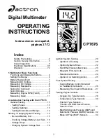
To measure Continuity (see Fig. 9):

1. Insert BLACK test lead into the COM

test lead jack.

2. Insert RED test lead into the  test lead

jack.

3. Turn multimeter rotary switch to 200

range.

4. Touch RED and BLACK test leads

together and view reading on display.

Display should read typically 0.2

 to 1.5

.

If display reading was greater than 1.5

,

check both ends of test leads for bad

connections. If bad connections are found,

replace test leads.

5. Connect RED and BLACK test leads

across component where you want to

check for continuity.

View reading on display:

• Continuity - Display reading is less than

10

.

• No Continuity - Display reading is greater

than 10

.

Testing Diodes

A diode is an electrical component that allows

current to only flow in one direction. When a

positive voltage, generally greater than 0.7V,

is applied to the anode of a diode, the diode

will turn on and allow current to flow. If this

same voltage is applied to the cathode, the

diode would remain off and no current would

flow. Therefore, in order to test a diode, you

must check it in both directions (i.e. anode-to-

cathode, and cathode-to-anode). Diodes are

typically found in alternators on automobiles.

Performing Diode Test (see Fig. 10):

Fig. 10

Cathode

Anode

Red

Black

2K 200

20M

2M

200K

20K

OHMS

750V AC
200V DC

COM

V

DWELL

CYL

CYL

CYL

CYL

Fig. 9

Red

Black

Summary of Contents for Digital Multimeter CP7676

Page 1: ...Air Flow MAF Sensors 34 Index Safety Precautions 2 Vehicle Service Information 3 Visual Inspection 3 Electrical Specifications 35 Warranty 72 1 Multimeter Basic Functions Functions and Display Defini...

Page 2: ...ge when the engine is running Always turn ignition key OFF when connecting or disconnecting electrical components unless otherwise instructed Always follow vehicle manufacturer s warnings cautions and...

Page 3: ...reconnected in the wrong place or not at all Don t take shortcuts Inspect hoses and wiring which may be difficult to see due to location Inspect the air cleaner and ductwork for defects Check sensors...

Page 4: ...n defines these features and functions and explains how to use these functions to make various measurements 1 Alligator Clip Adapters Some multimeter tests and measurements are more easily done using...

Page 5: ...s used for measuring DC Direct Current Voltages in the range of 0 to 200V 8 AC VOLTS This Function is used for measuring AC Alternating Current Voltages in the range of 0 to 750V 9 DISPLAY Used to dis...

Page 6: ...or in other words the value being measured is larger than the current range The range should be increased until a value is shown on the display If you are in the highest range and the multimeter is s...

Page 7: ...d electrical wiring and appliances To measure AC Voltages 1 Insert BLACK test lead into the COM test lead jack 2 Insert RED test lead into the V test lead jack 3 Connect RED test lead to either side o...

Page 8: ...ad jack 3 Connect RED test lead to positive side of voltage source 4 Connect BLACK test lead to negative side of voltage source NOTE If you don t know which side is positive and which side is negative...

Page 9: ...n or shorted wires To measure Continuity see Fig 9 1 Insert BLACK test lead into the COM test lead jack 2 Insert RED test lead into the test lead jack 3 Turn multimeter rotary switch to 200 range 4 To...

Page 10: ...election 6 Measure engine RPM while engine is cranking or running 7 View reading on display Fig 11 Black Ground Red Typical Ignition Coil 1 Insert BLACK test lead into the COM test lead jack 2 Insert...

Page 11: ...2 Insert RED test lead into the test lead jack 3 Connect RED test lead to DWELL signal wire If measuring DWELL on breaker point ignition systems connect RED test lead to negative side of primary ignit...

Page 12: ......

Page 13: ...to see if a switch Opens and Closes properly To test Switches see Fig 14 1 Insert BLACK test lead into the COM test lead jack 2 Insert RED test lead into the test lead jack 1 Insert BLACK test lead i...

Page 14: ...jack 2 Insert RED test lead into the V test lead jack 3 Turn multimeter rotary switch to 200 range Most solenoids and relay coil resistances are less than 200 If meter overranges turn multimeter rota...

Page 15: ...any starting charging system checks you must first test the battery to make sure it is fully charged 4 Insert RED test lead into the V test lead jack 5 Disconnect positive battery cable 6 Connect RED...

Page 16: ...below Fig 17 Voltage Temperature 9 6V or greater 70 F and Above 9 5V 60 F 9 4V 50 F 9 3V 40 F 9 1V 30 F 8 9V 20 F 8 7V 10 F 8 5V 0 F If voltage on display corresponds to above voltage vs temperature...

Page 17: ...h this test you can find excessive resistance in the starter system This resistance restricts the amount of current that reaches the starter motor resulting in low battery load voltage and a slow cran...

Page 18: ...Load the electrical system by turning on the lights windshield wipers and setting the blower fan on high 11 View reading on display Voltage should not drop down below about 13 0V 12 Shut off all acce...

Page 19: ......

Page 20: ...teps 6 and 7 for remaining ignition coils Fig 20 Fig 21 Black Secondary Coil Primary Coil Red 4 Insert RED test lead into the V test lead jack 5 Turn multimeter rotary switch to 200 range Touch RED an...

Page 21: ...ry ignition coils is 6 0 30 0K Refer to vehicle service manual for your vehicles resistance range 15 Repeat test procedure for a HOT ignition coil NOTE It is a good idea to test ignition coils when th...

Page 22: ...sult if other means of removal are attempted Refer to vehicle service manual for procedure NOTE Some spark plug wires have sheet metal jackets with the following symbol This type of plug wire contains...

Page 23: ...hicle service manual for pin locations 3 Insert BLACK test lead into the COM test lead jack 4 Insert RED test lead into the V test lead jack 5 Connect RED test lead to sensor SIGNAL pin 6 Connect BLAC...

Page 24: ...or Fig 24 Test Procedure see Fig 24 1 Insert BLACK test lead into the COM test lead jack 2 Insert RED test lead into the V test lead jack 3 Connect RED test lead to either sensor pin 4 Connect BLACK t...

Page 25: ...e to the vehicle engine computer refer to vehicle service manual for location of this wire For all vehicles with distributors connect RED test lead to negative side of primary ignition coil refer to v...

Page 26: ...ltimeter rotary switch to 6 Cylinder Dwell position for all GM vehicles 4 Run engine at 3000 RPM 5 Make engine run both RICH and LEAN 6 Watch multimeter display 7 Multimeter display should vary from 1...

Page 27: ...correct units If display reading is 10 or less subtract test lead resistance found in Step 3 from above reading Compare reading to manufacturers specifications for fuel injector coil resistance This i...

Page 28: ...nce indicates a lean exhaust too much oxygen while a high voltage low resistance indicates a rich exhaust not enough oxygen The computer uses this voltage to adjust the air fuel ratio The two types of...

Page 29: ...ame to deplete sensor of oxygen Rich Condition Multimeter display should read 0 6V or greater for Zirconia Type Sensors an Ohmic Resistance value for Titania Type Sensors Reading will vary with flame...

Page 30: ...nsors leave multimeter test leads still connected to sensor 11 Heat up sensor If testing Intake Air Temperature Sensor To heat up sensor dip sensor tip into boiling water or Heat tip with a lighter if...

Page 31: ...see Fig 29 1 Insert BLACK test lead into the COM test lead jack 2 Insert RED test lead into the V test lead jack 3 Disconnect wiring harness from sensor 4 Connect Test Leads Connect RED test lead to s...

Page 32: ...ce as sensor is opened and closed Bad Sensor There is no change in resistance as sensor is opened or closed 32 Manifold Absolute Pressure MAP and Barometric Pressure BARO Sensors This sensor sends a s...

Page 33: ...frequency type MAP sensors refer to vehicle service manual for MAP sensor specifications It is O K if last two display digits change slightly while vacuum is held constant Remember to multiply displa...

Page 34: ...e ground 4 Connect RED test lead to MAF signal wire Refer to vehicle service manual for location of MAF signal wire You may have to backprobe or pierce MAF signal wire in order to make connection Refe...

Page 35: ...RPM conversions 9 Test Results Good Sensor Sensor output voltage or frequency RPM are within manufacturers specifications at Key ON Engine OFF Sensor output voltage or frequency RPM increase with inc...

Page 36: ...36...

Page 37: ...te GARANTIA COMPLETA DE UN A O SPX Corporation 15825 Industrial Parkway Cleveland Ohio 44135 EE UU garantiza al usuario que esta unidad estar libre de defectos de materiales y mano de obra por un 1 a...

Reviews: