background image

29

ORDER NOW


>


1800 267 267


>


activemedicalsupplies.com.au

Sovereign Wheelchair

8 Accessories

8.1   

Tilt Protection / Anti-tilt Rollers

Always use the anti-tilt mechanism in pairs.

To mount tilt protection, proceed as follows.
•  Remove the rubber profiles of the tip assist
•  Push the round profile for the tilt protection 

onto the lower side frame tube.

•  Attach the tilt protection with the M6x35 

bolt and locknut M6 in the hole in the frame 
provided.

When the anti-tilt rollers are raised, the tilt 
protectors can also be used for tipping assistance.

Fig. 40

Fig. 41

8.2   

Safety Belt

If required, a safety belt is available as an 
accessory. This is mounted on the side frame of the 
wheelchair with the side part either temporarily 
removed or swung away (Fig. 42). Take the open 
end of the belt once around the side frame tube 
and fix it with the belt buckle. 
Length adjustment is also carried out with the belt 
buckle. Adjust the belt length such that the belt sits 
firmly but does not apply pressure.

Fig. 42

Summary of Contents for Sovereign

Page 1: ...Sovereign Wheelchair Instructions for Use Issue 1 ...

Page 2: ...he wheelchair 9 6 Assembly and adjustments 11 6 1 Folding and unfolding 11 6 2 Legrests 12 6 3 Side parts 15 6 4 Armrests 16 6 5 Seat 17 6 6 Wheel base 20 6 7 Brakes 21 6 8 Backrest 23 6 9 Push handles 24 6 10 Wheels and tyres 25 6 11 Quick release axles 27 6 12 Tip assist 27 7 Options 28 7 1Horizontally adjustable legrests 28 8 Accessories 29 8 1 Tilt protection 29 8 2 Safety Belt 29 ...

Page 3: ... data 31 11 Transport 32 11 1 Transporting the wheelchair 32 11 2 Seating a disabled vehicle 32 12 Storage and shipment 38 13 Information on re use 38 14 Repairs 39 15 Disposal 39 16 Appendices 40 Care hygiene and maintenance guidelines 40 Hygiene and risk evaluation 41 Warranty 42 Maintenance plan 43 ...

Page 4: ...ght e g strong upper body movements or overcoming obstacles Steps and larger obstacles may only be crossed with the help of at least two assisting persons For this use lifting points 1 and 2 see overview of the wheelchair If equipment such as ramps lifts or step climbing aids are available these should be used When using on a downward incline it must be noted that a danger of tipping exists from 1...

Page 5: ...ecome hot Caution Danger of burning We recommend that leather gloves are used for use outdoors These increase grip and protect fingers and hands from dirt and injury at the same time Please note that padded parts can become hot in direct sunlight and lead to skin injury on contact Therefore cover these parts or protect the wheelchair from direct sunlight When transferring between wheelchair and be...

Page 6: ...ted Information and recommendation regarding vehicle restraint systems can be sourced from your health professional or local Department of Transport A wheelchair secured in a vehicle will not provide the equivalent level of safety and security as a vehicle seating system It is always recommended that the user transfers to the vehicle seating system where appropriate Please ensure the restraint sys...

Page 7: ...standard wheelchair no longer offers the required safety Use of the wheelchair is not suited for perception disorders severe disturbances of equilibrium loss of limbs on both arms contractures damage to joints on both arms inability to sit reduced or insufficient eyesight 3 Purpose The wheelchair is produced solely for increasing mobility and for the transport of people with impaired mobility in a...

Page 8: ...rton Supply assembly and instruction in use of the wheelchair is carried out by the qualified medical supplies retailer If delivered by rail or a forwarding agent the product is to be checked with regard to transportation damage at once in the presence of the shipper If there is any damage note the following Record the facts Produce a statement of assignment All claims from the damage are assigned...

Page 9: ...s for the written instructions The following illustrations should help to identify the names and interaction of the individual elements See Fig 1a 1b and 1c PLEASE NOTE The text passages that are identified specially with Backrest cover Armrest cushion Combined side part Seat cover Side part lock Locking brake knee lever Foot plate Leg rest Steering wheel Steering wheel axle Lifting point 1 Fig 1a...

Page 10: ...10 Instructions for Use Hand push handles Side part Drive wheel Lifting point 2 Tip assist Wide seat Double cross brace Footrest extension Push rim Fig 1b Fig 1c ...

Page 11: ... 3 Now press with the flat of the hand against the seat tube nearest you to unfold the wheelchair Fig 4 When unfolding please ensure that your fingers remain on the seat belt There is otherwise a danger of jamming Folding Position your wheelchair next to you Tip by pulling the backrest to you until the weight is taken off the opposite driving wheel At the same time pull the seat cover upwards unti...

Page 12: ...e for the quick release axle and push the legrests with the guide profile into the hole in the frame Fig 6 Now the legrest is simply folded forwards and locks automatically in place Before moving off check for firm attachment of the legrests 6 2 3 Removing the legrests To transport your wheelchair as compact as possible you can completely remove the legrests and foot plates Fig 7 Pull the handle t...

Page 13: ...tes upwards first To return to the original position simply swing the legrest forwards until it locks into place When standing up from the wheelchair under no circumstances stand on the foot plates 6 2 5 Setting the legrest length The length of the legrests can be adjusted in 520mm steps up to a total of 80mm To do so remove the Allen bolt 4 mm and set the legrest as required Fig 9 6 2 6 Angle adj...

Page 14: ...u can adjust the width of the foot plates to meet your needs Loosen the fastening screw on the foot plate then you can adjust the foot plate to a narrower or wider setting 105mm to 155mm Then secure the foot plate by firmly tightening the fastening screw Fig 11 ...

Page 15: ... first swing it forwards and allow it to click into place with light pressure on the armrest When moving the side parts ensure that no items of clothing or other times can become jammed Before use check for firm attachment of the side parts 7 3 1 Removing the side parts For ease of getting into or out of the wheelchair removing a side part can be helpful To do this loosen the front locking lever a...

Page 16: ...rest upwards or downwards When you let go of the knob the armrest automatically locks into position 6 4 2 Position of the armrests You can shift the armrests further forwards or backwards To do this you operate the knob located at the side of the armrest and pull this towards the front or the back When you let go of the knob the armrest automatically locks into position Fig 15 Fig 16 ...

Page 17: ...ncreased significantly Anti tilt rollers or an extended wheelbase are then necessary Check the settings first with a helper Only use settings that you feel safe with Step 2 Remove the Allen bolts at the back on the seat cover see Fig 18 Pull the adapter out to the required position and then retighten the bolt Step 3 pull back the rear part of the seat cover and connect this again with the front se...

Page 18: ...ut tight again and fasten the drive wheel 2 Front wheel height The height of the front wheels can be adjusted to three levels Loosen the Allen bolt see fig 21 and pull out the wheel axle Move the front wheel to the desired height then tighten the bolt again 3 Angle of the steering wheel axle The angle of the steering wheel axle can change as a result of changing the height of the drive wheel and o...

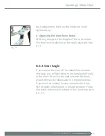
Page 19: ...r brake has to be newly adjusted see 6 7 6 5 3 Seat Angle If you incline the seat of the wheelchair towards the back you will be sitting more deeply and firmly in the chair To incline the seat towards the back attach the quick release axle in a higher position If you wish to incline the seat towards the front fix the quick release axle in a lower position Fixing the quick release axle is done in t...

Page 20: ...e wheel base On the other hand shortening the wheel base improves manoeuvrability A shortening of the wheelbase is only recommended for practised wheelchair users To set the wheelbase loosen the four fastening screws that secure the wheel attachment The wheelbase can be adjusted in four stages Fasten the wheel attachment afterwards in the cut outs provided Ensure that all four screws are securely ...

Page 21: ... the same time check for even wear of the tyres If the profile depth in the middle of the tread is less than 1mm the tyre must be changed If you have the necessary technical experience you can change the tyre yourself if you do not feel confident to do this yourself your specialist retailer will be able to help you Now check the adjustment of the brake This must be set such that the gap between th...

Page 22: ...only operate on one driving wheel each Ensure that both drive wheels have the same tyre pressure with pneumatic tyres to achieve good directional stability After completion of the setting process retighten the loosened bolts and test the brakes ...

Page 23: ... Velcro tape See Fig 30 Then you can adjust each of the belts so that they are firmer or less firm Fig 31 To lessen the tension on particular parts of your back loosen the belt there a little Now you have to re secure the back padding by means of the Velcro tape Backrest height To adjust the backrest height it is recommended that the side parts and the back padding are removed first You can then l...

Page 24: ...he push handles can be adjusted to make it comfortable for an accompanying person to push you Loosen the lever screw Fig 33 on the push handles and adjust them to the required height Then firmly tighten the lever screws again to lock the push handles Fig 33 ...

Page 25: ...see Section 6 11 Check that the wheels sit firmly each time they are attached Drive wheels Rubber tyres with an inner tube or PU tyres puncture proof no valve size 24 x1 model 1321 24 x 1 3 8 are fitted as standard on your Standard size model If they become worn or defective the authorised specialist retailer should be requested to undertake the repair To ensure optimum operating safety of the bra...

Page 26: ...ing safety of the brakes wheelchair the pneumatic tyres must have a pressure of 200 250 kPa 2 2 5 bar Push Rims The push rims attached to the drive wheels can be mounted a little further outwards so that you can grip them better Changing the push rim position raises the danger of your fingers being squeezed or jammed First loosen the four bolts Fig 36 used to attach the push rims to the drive whee...

Page 27: ...ck into the mount At the same time press the locking button Ensure when pushing back in that the quick release axle is pushed Check after pushing back in that the wheel is firmly attached by pulling it towards you without operating the locking button of the quick release axle Fig 37 6 12 Tip Assist The tip assist can be used to help an accompanying person overcome obstacles such as kerbs Hold the ...

Page 28: ... adjust the legrests and the legrest length please refer to Section 6 2 Horizontal adjustment functions as follows see Fig 39 Pull lever backwards Bring the legrest into the position required by raising or lowering the support tube for the legrest Release the lever The legrest locks automatically Fig 39 ...

Page 29: ...d locknut M6 in the hole in the frame provided When the anti tilt rollers are raised the tilt protectors can also be used for tipping assistance Fig 40 Fig 41 8 2 Safety Belt If required a safety belt is available as an accessory This is mounted on the side frame of the wheelchair with the side part either temporarily removed or swung away Fig 42 Take the open end of the belt once around the side ...

Page 30: ...g and moving onto or turning on inclines Leaning a long way out of the wheelchair increases the danger of tipping For increased safety all wheelchairs can be fitted with a safety belt not standard To get over obstacles more easily the assisting person must position the wheelchair at the correct angle to the obstacle by pressing on the tip assist Fig 42 Before getting in or out the locking brake mu...

Page 31: ... 3 8 pneumatic Steering Wheels standard 250 x 50mm puncture proof Drive Wheels optional 250 x 50mm pneumatic tyres other sizes are also available Side Parts height and depth adjustable Legrests removable swing away lower leg length is adjustable optionally horizontally adjustable angle and width of the foot plates are adjustable Seat and Back Covers high quality washable breathable and easy care n...

Page 32: ...achment points are not authorised by the manufacturer Where possible use a fixed fitted car seat and its seatbelt system Stow the folded wheelchair in the boot The person responsible for transportation should be familiar with the current regulations on transportation and use of the disabled vehicle and restraint system 4 point restraint systems anchored to the vehicle must be used to restrain the ...

Page 33: ...s When used as a seat in a disability vehicle a 3 point safety belt must always be worn Other fixation systems and straps may be used in addition If your wheelchair has an adjustable backrest or seat these must be placed in as vertical a position as possible and the locking mechanism checked Products that have been involved in an accident must be replaced and are no longer licensed to transport pe...

Page 34: ...l stability D 300mm The hatched area indicates the range within which the straps must be attached to the floor Wheelchair must not be placed in front of an active air bag Deactivate air bag or have it deactivated Check whether the straps conform to the angles in Fig D below Fig C Rear View Position of static or retracting belts Position of static or retracting belts Side View Rear attachment point...

Page 35: ... and pull over the base plate Detach the mono fittings by pulling down from the base plate Attachment to wheelchair Attachment to the wheelchair may be by securement points Fig G or tie down system Fig H to the labelled points Under no circumstances attach the strap to the footrests or other detachable parts Tensioning and loosening the straps Tension using handle Fig I Loosening using lever or al...

Page 36: ...licks into place The lock is opened by pressing the large button The safety belt should fit firmly but not cut in To tighten the belt pull on the loose end of the belt You can further adjust the belt by pushing the clasp forwards in the open position The shoulder belt hooks into the lap belt It must fit close to the body across the pelvis chest and over the shoulder Place the clasp in front of the...

Page 37: ...ign Wheelchair Belts must not run across wheelchair attachments such as armrests or wheels Fig L Fig M In order to be able to remove the belt quickly in the event of an accident a seat belt cutter like this Fig N should be kept in every vehicle Fig N Fig L Fig M ...

Page 38: ...store it for this purpose so that it is available if required Then your wheelchair is optimally protected against environmental influences during storage or transport 13 Information on Re Use The Sovereign Wheelchair is suitable for re use For further use the wheelchair must first be thoroughly cleaned and disinfected in accordance with the attached care and maintenance instructions Subsequently t...

Page 39: ...u by telephoning our customer service Tel 1800 267 267 15 Disposal Even a wheelchair that can no longer be used represents valuable material that can be recycled into the industrial process Therefore never throw away your wheelchair for disposal in the household waste but have it disposed of professionally in an official waste disposal centre Your local waste service will be pleased to advise you ...

Page 40: ...he user Beyond this regular care of the product should guarantee proper functioning even after long use We have prepared some care tips a hygiene plan and a maintenance table for you below We hope to have provided a good overview of the most important care hygiene and maintenance work for your product Care Instructions Cleaning of the seat and back covers can be undertaken with warm water and a sp...

Page 41: ...giene plan and risk evaluation of medical products before preparation In accordance with the second amendment to the medical products act 2 MPG ÄndG of 13 December 2001 here Article 11 Section 4 Para 2 amendment to the medical devices operator ordinance Date 29 04 2005 1 Product Sovereign Wheelchair 2 Risk Level Non critical medical product Medical product that only comes into contact with unbroke...

Page 42: ...Wipe dry treated areas with paper towel Repeat if necessary 4 Dispose of protective gloves and paper towels 7 Special Identification Not necessary 8 Sterilisation Not necessary 9 Critical Process Steps Special Requirements Replacement of the seat and back covers recommended Warranty The manufacturer states that the Sovereign wheelchair has a 12 month warranty against material or production defects...

Page 43: ... the user or an assistant Use a tyre pressure gauge Caution Tyre pressures that are too low have a negative effect on braking behaviour Visual check by the user With worn out tyre treads or damage to a tyre have them replaced by an authorised specialist workshop Every 4 weeks depending on frequency of use Oil moving parts All moving points of the cross brace Moving parts on the side parts Brake le...

Page 44: ...35 Southgate Avenue Cannon Hill QLD 4170 P 07 3899 8887 sales activemedicalsupplies com au activemedicalsupplies com au Sovereign Wheelchair Instructions for Use Issue 1 ...

Reviews: