background image


CARE & MAINTENANCE INSTRUCTION 


It is important to perform the following maintenance inspections at the beginning of each season and twice monthly 

thereafter.     


*


Inspect all nuts and bolts for tightness and tighten as required. It is particularly important that this procedure 
be followed at the beginning of each season. 

*


Remove plastic swing seats slide and take indoors or do not use when temperature drops below 32

˚

F (0

º

C). 

*


Inspect swing seats, ropes, cables and chains for evidence of deterioration. Replace as needed. 

*


Inspect all coverings for bolts and sharp edges to be certain they are in place. Replace when necessary. 

*


Oil all metallic moving parts monthly during the usage period. 

*


Inspect metal tubing and slide bed for damage and sharp edges.    Replace when necessary. 

*


Sand rusted areas on metal tubing and repaint using a nonlead-based paint meeting the requirements of Title 
16 CFR Part 1303. 

*


If slide bed is exposed to direct sunlight, always check bed to ensure it is not too hot for children use.    Pour 
cold  water  onto  the  slide  bed  until  it  cools.    Inspect  slide  bed  periodically  during  use.    Replace  when 
necessary. 

*


Plastic components should be replaced every three years. 


DISPOSAL INSTRUCTIONS 


*


When it is time to dispose of the playground equipment, please use care when disassembling the playground 
equipment.    Dispose in a safe place and manner so as not to present any hazards to any individual.    Wear 
heavy duty working gloves! 

*


Be sure to completely disassemble the whole swing and slide sets, before disposal.   

*


Do not leave partially disassembled equipment in area where accessible by children. 

*


Consumer may wish to recycle the steel tubing, please take the frame to your local recycling centre. 

*


All plastic part could be recycled, take it to your local recycling centre. 

*


Do not let children play with any disassembled parts destined for disposal, such as chain, slide, tubings, bolts, 
nuts, screws! 

CAUTION 

Do not allow children to use the swing set until the maintenance has been carried out.   

The  use  of  the  swing  set  not  in  first  class  condition  exposes  the  child  to  the  risk  of  injury.  As  a  parent, 

supervisor, owner or guardian, it is your responsibility to ensure that the swing set  is properly maintained. 

Spare parts are available through The Warehouse Customer Service centre – 0800422 274 


Marketed by: 

The Warehouse 

26 The Warehouse Way 

Northcote 


Summary of Contents for S001S

Page 1: ...nual Model S001S Un IMPORTANT Read all instructions carefully before using this product Retain this owner s manual for future reference The specification of this product may vary from this photo subje...

Page 2: ...Y INSTRUCTIONS 2 CARE MAINTENANCE INSTRUCTION 4 PARTS LIST 6 ASSEMBLY INSTRUCTIONS 10 Customer service number 0800 422 274 MON FRI 8AM 5PM SAT SUN 9AM 4PM Marketed By The Warehouse LTD 26 The Warehous...

Page 3: ...uipment sits on level ground To prevent serious injury to children the playground equipment must not be used until properly assembled and anchored Do anchor all playground equipment Do not install ove...

Page 4: ...ially hazardous to users Verify that suspended climbing ropes chain or cable are secured at both ends and verify that suspended climbing ropes chain or cable cannot be looped back on itself Instruct c...

Page 5: ...iodically during use Replace when necessary Plastic components should be replaced every three years DISPOSAL INSTRUCTIONS When it is time to dispose of the playground equipment please use care when di...

Page 6: ...at these materials are installed and maintained at 6 9 and 12 inches deep However consumers should recognize that no matter what type of surface material is used it can not prevent all injuries due to...

Page 7: ...re If you intend to install Not included Anchor this is needed Flat Head and Philips Wrench Head Screwdriver included Not included Allen Wrench included Parts list for main frame assembly A1 LEF TOP B...

Page 8: ...6 SPRING WASHER 4 PCS Parts list for swing seat J1 PVC COVERED CHAIN PREASSEMBLED 4 PCS J3 EYE BOLT WITH ATTACHMENT BOLT PREASSEMBLED 4 PCS J4 EYE BOLT PREASSEMBLED 4 PCS K1 SWING SEAT 2 PCS Hardware...

Page 9: ...ride assembly L4 BRACKET 1 PC L5 BRACKET CLAMP 1 PC L6 WASHER 4 PCS N2 BOLT 5 16 25 2 PCS N8 NYLON NUT 5 16 2 PCS N14 PLASTIC CAP 2 PCS Hardware used for glide ride assembly N1 BOLT 1 4 35 4 PCS N2 BO...

Page 10: ...C X5 SLIDE FRONT SUPPORT 1 PC X6 SLIDE LADDER STEPS 2 PCS Y2 SLIDE 1 PC Hardware used for slide assembly Y1 PLASTIC CONNECTOR 2 PCS Z1 BOLT1 4 35 6 PCS Z2 BOLT1 4 60 2 PCS Z3 BOLT1 4 100 2 PCS Z4 WASH...

Page 11: ...sphalt packed earth or any other hard surface A fall onto a hard surface can result in serious injury to the user TIGHTENING NUTS BOLTS Do not over tighten the nuts and bolts when you are assembling y...

Page 12: ...11 Step 1 Insert A1 into the other end of A2 secure with B1 B5 B4 and B3 HINT Please make sure that concave hole faces down...

Page 13: ...12 Step 2 Insert small end of A4 into the socket at the end of A1 align holes on them Secure with B1 B5 B4 and B3 Then attach the other two pieces of A4 on the other side to A2 the same...

Page 14: ...13 Step 3 Secure with B1 B5 B4 and B3 Secure with B2 B6 B4 and B3 Insert A5 into A4 align holes on them Attach A6 to A5 Repeat above to assemble the other A7 to A5 that is attached to the end of A2...

Page 15: ...14 Step 4 Insert J3 into holes on A1 A2 Secure it with J8 J9 and J6 Step 5 J4 and K1 are PRE ASSEMBLED if you find it loosely please follow below step Attach K1 to J4 Secure with J7 J9 and J6...

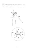
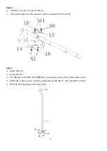
Page 16: ...w driver to tighten the N3 and N8 Step 7 Attach M5 to L1 Secure N5 N13 M1 M2 and L1 are PRE ASSEMBLED if you find it loosely please follow below step Attach M1 to the top of L1 and then align holes on...

Page 17: ...N2 and N11 Step 9 Insert 2xM3 into L2 then attach L3 to L2 with N6 lightly secure N6 with N9 Do not tighten completely Attach the other L1 L2 and L3 by the as way as described above once this is done...

Page 18: ...17 Step10 Attach M4 to L2 Secure using N1 N9 N7 and N11 Step 11 Attach X5 to Y2 Secure using Z7 and Z1 Attach X4 to Y2 NOTE Make sure that the bolt holes face up...

Page 19: ...d in position Step 13 Insert the end of X4 into X1 secure using Z2 Z4 and Z5 In the same way fix the other end of x4 with X2 Insert Z1 into Z4 and insert into X1 X2 and X3 as shown Insert Z8 into Z4 a...

Page 20: ...19 Step 14 Attach Y1 to X1 and A7 secure using Z3 Z7 and Z4 Z5 Step 15 Go back to secure Z3 and Z5 to X1 now Tighten all screws...

Page 21: ...ment is firmly anchored cementing is usually recommended When equipment is cemented do not bury the legs more than three inches below the ground surface This will ensure sufficient space remains under...

Page 22: ...use shovel to crave out the lower part of the hole to create a large diameter hole bottom Place 2 inches brick or gravel bed as shown in drawing below Use about 45lb of concrete per leg Cover concret...

Reviews: