9.6
SUB wiring
9.6
SUB wiring
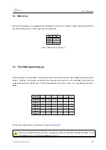
When the UT26 processor is equipped with the SUB option (section
), a sub-bass output is delivered on the BCL
port of the UT26 processor. Table
describes the wiring used.
Pin
Sig
pin 5
+
pin 6
-
pin 14
Ground
Table 6: SUB wiring on BCL port.
10
Test before powering up
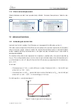
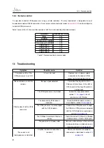
Before powering up an installation, it is good practice to ensure that the column cable is properly connected to the
column. Therefore, the electrical resistance of each channel of the column must be controlled at the end of the
cable connected to the amplifier side. The measured electrical resistances values must correspond to the values
below.
Channel
1
2
3
4
5
6
SA100P
6
.
6Ω 6
.
6Ω 6
.
6Ω
SA180P
6
.
6Ω 6
.
6Ω 6
.
6Ω
SA250P
6
.
6Ω 6
.
6Ω 6
.
6Ω 4
.
4Ω 4
.
4Ω 4
.
4Ω
SA400P
6
.
6Ω 6
.
6Ω 6
.
6Ω 6
.
6Ω 6
.
6Ω 6
.
6Ω
SA180S
6
.
6Ω 6
.
6Ω 6
.
6Ω
SA250S
3
.
3Ω 6
.
6Ω 6
.
6Ω 4
.
4Ω 4
.
4Ω 3
.
3Ω
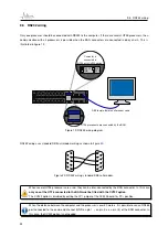
For details on connector pin assignement, see figure
When measuring the electrical resistance, the cable resistance must be taken into account (about
1
.
3Ω
for
100 meters of
1
.
5
mm
2
;
0
.
7Ω
for 100 meters of
2
.
5
mm
2
).
Last update: December 23, 2010
25


