background image

Page 2

PRO-MUX-1 Configuration Guide

Setup Wizard

Selecting the set-up wizard option will go to a page where all pre-existing user defined configura

-

tions can be modified, and a new configuration can be created for the device. The following page 

will appear when the setup wizard option is selected:

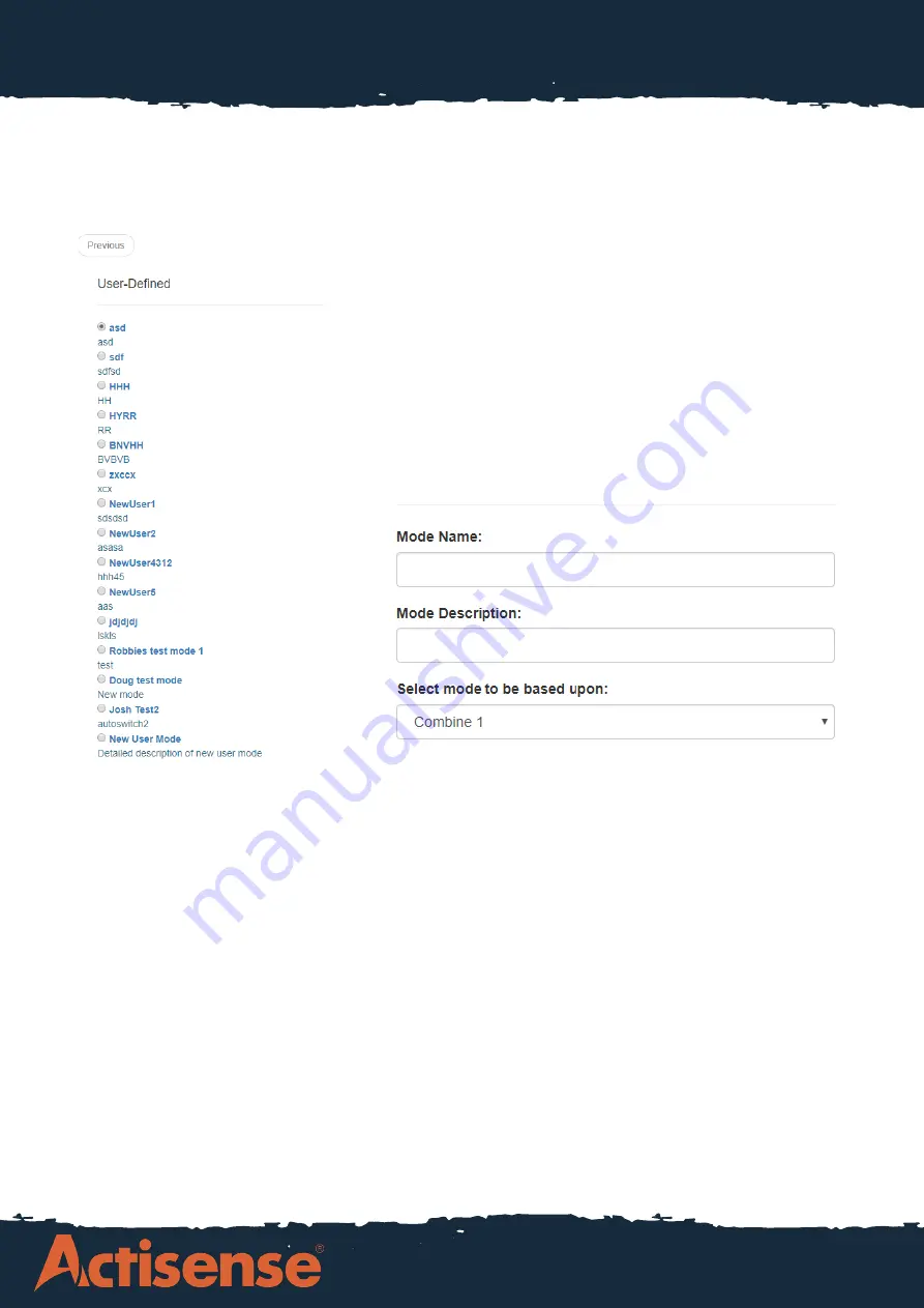
If the device is being used for the first time, there will be 

no options other than ‘New User Mode’ in this page as it 

will be a new configuration for the first time. 

Once the New User Mode option is selected, the page 

presented will allow for a custom name and description 

to be given to the configuration, and a mode to base 

the new configuration from using another user defined 

mode:

Once the mode has been named and a base configuration selected, the baud rate configuration 

page will be shown. Here the baud rate is individually configurable for each input port and output 

port, and a ‘friendly name’ can be given to each port. There are two routes that can be taken here 

for talker devices connected to the inputs:

1. The device is left on the autobaud configuration, meaning that the PRO-MUX-1 will adjust the 

baud rate on each input port dependant on the baud rate of the talker device connected to it.


(Au

-

tobaud is only available on Ports 1-4. 5-8 are fixed to 4800 baud).

2. The device can be configured for each port manually, giving the user more control over the con

-

figuration if the autobaud feature is not preferred.


After configuring the Input ports, the Output ports can be configured. The Output ports can be set 

up to either follow the baud rate on the chosen Input or set to a manually selected value. It is im

-

portant to highlight that only Output 1 can be set to 115200 baud, whilst the rest of the ports have 

a maximum baud rate of 38400. 

Warning: Manually setting the output baud rate slower than the input baud rate may result in the 

loss of data due to limited bandwidth. Consult the Stats page to view the output loading. The Sta

-

tus LED on PRO-MUX-1 will also indicate overload status - consult user manual.

Summary of Contents for PRO-MUX-1

Page 1: ...Page 1 PRO MUX 1 Configuration Guide How To Configure the PRO MUX 1 Multiplexer ...

Page 2: ...m our website For the example used here the device is connected to a DHCP network router via an Ethernet cable To connect to the device enter http promux xxxxxx into any web browser xxxxxx is replaced by the serial number e g promux 123456 Once the device has been connected to the following web page will appear This is the home page for the web interface giving an overview of product info includin...

Page 3: ...iven to each port There are two routes that can be taken here for talker devices connected to the inputs 1 The device is left on the autobaud configuration meaning that the PRO MUX 1 will adjust the baud rate on each input port dependant on the baud rate of the talker device connected to it Au tobaud is only available on Ports 1 4 5 8 are fixed to 4800 baud 2 The device can be configured for each ...

Page 4: ...ser to identify various states and have a message sent by the PRO MUX 1 to identify what Alarm has trigged Message must be enabled by ticking Action Send Message option for each alarm Autoswitch PRO MUX 1 will Autoswitch if enabled between one or more inputs and will output the following message if Autoswitch is performed MXALR hhmmss 004 PRO MUX 1 206221 Autoswitch Data Overload PRO MUX 1 will de...

Page 5: ...ood amount of control over the Inputs and Outputs however some times it is required to go further into the connections and define what messages specifically from each Input device are sent to each Output This is where advanced routing comes in For example if the USG 2 on IN 4 is sending 7 messages but only 3 of these are required for the NGW 1 then the advanced routing can be used to filter out un...

Page 6: ... tick box for ASW 1 or and ASW 2 it enables the Autoswitch function on the de vice and by selecting the Config button it will prompt a second dialogue box to appear where the priority of the devices can be defined As seen in this screenshot the PRO MUX has been configured on ASW1 to have IN1 as the prima ry and to switch to IN2 as the secondary if IN1 fails The priority is defined from left to rig...

Reviews: