
General
One metre of halogen free low smoke and fume electric cable is fitted to each control mode for convenience of onsite wiring. This provides
the distinct safety advantage of all electrics terminating outside the duct, eliminating potential in-duct fire hazards from wiring faults. The
Electrical Thermal Release is prewired with 0.5m halogen free low smoke and fume cabling to Control Modes 5 and 6.
A Manual test switch fitted on the ETR allows periodic operation of damper, simulating actual fail-safe release under smoke/fire conditions.
Control Mode Wiring Procedure
If integrating this unit with an Actionpac damper control system (LNS, EMS or EMB) please refer to the relevant catalogue and specific
project details.
WHITE (2)
BLACK (1)
1
2
3
4
5
6
_
+
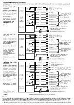
SUPPLY 24V A.C. or D.C.
TYPICALLY 10W (MOTORING
2W (RESET)
COMMON
CONTINUITY WITH 'COMMON'
WHEN DAMPER CLOSED
COMMON
VOLT FREE CONTACT
MADE BETWEEN 1 & 2
WHEN DAMPER
FULLY RELEASED
VOLT FREE CONTACT
MADE BETWEEN 4 & 6
WHEN DAMPER
FULLY RESET
M
AC/DC 24V
50 / 60 Hz
12.5 VA
10 / 2 W
Imax
8.3A @ 5ms
-30°C...+50°C
CONTINUOUS
Smoke Shield Mode 5 PTC
(24V System)
Supply on - Damper motors open
Supply off - Damper spring close
Electrical thermal release (ETR)
(Must be fitted to ducting for
damper operation)
Spring close time ˜ 22 seconds
Motor open time ˜ 60 seconds
(Connect 24V via a safety
isolating transformer.)
IP54 rated
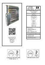
Smoke Shield Mode 6 PTC
(230V System)
Supply on - Damper motors open
Supply off - Damper spring close
Electrical thermal release (ETR)
(Must be fitted to ducting for
damper operation)
Spring close time ˜ 22 seconds
Motor open time ˜ 60 seconds
(To isolate from main power
supply, the system must
incorporate a devise which
disconnects the phase
conductors, with at least 3mm
contact gap)
120V A.C. version available
IP54 rated
ELECTRICAL THERMAL RELEASE (ETR)
(MUST BE FITTED TO DUCTING FOR
DAMPER OPERATION).
(SPRING BIASED TEST SWITCH)
TF 72°C
AC
250V
6(3)A
BROWN
BLUE
1
2
3
4
5
6
L1
SUPPLY 230V AC 50/60Hz
TYPICALLY 12W (MOTORING
4W (RESET)
COMMON
COMMON
VOLT FREE CONTACT
MADE BETWEEN 1 & 2
WHEN DAMPER
FULLY RELEASED
VOLT FREE CONTACT
MADE BETWEEN 4 & 6
WHEN DAMPER
FULLY RESET
M
AC/DC 24V
50 / 60 Hz
14 VA
12 / 4 W
-30°C...+50°C
CONTINUOUS
ELECTRICAL THERMAL RELEASE (ETR)
(MUST BE FITTED TO DUCTING FOR
DAMPER OPERATION).
(SPRING BIASED TEST SWITCH)
TF 72°C
AC
250V
6(3)A
N
CONTINUITY WITH 'COMMON'
WHEN DAMPER OPEN
CONTINUITY WITH 'COMMON'
WHEN DAMPER CLOSED
CONTINUITY WITH 'COMMON'
WHEN DAMPER OPEN
CONTINUITY WITH 'COMMON'
WHEN DAMPER CLOSED
CONTINUITY WITH 'COMMON'
WHEN DAMPER OPEN
CONTINUITY WITH 'COMMON'
WHEN DAMPER CLOSED
CONTINUITY WITH 'COMMON'
WHEN DAMPER OPEN
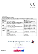
Smoke Shield Mode 5-3P PTC
(24V System)
Supply on - Damper motors open
Supply off - Damper spring close
The M5-3P-1 is controlled by a
standard 0...10V control signal.
The actuator motors to the
position specified by the control
signal. If the ETR is activated,
power supply lost or removed the
device springs the damper to the
fail-safe position.
Electrical thermal release (ETR)
(Must be fitted to ducting for
damper operation)
Spring close time ˜ 16 seconds
Motor open time ˜ 120 seconds
The SiHF connecting cable
needs to be protected from sharp
edges.
(Connect 24V via a safety
isolating transformer.)
IP54 rated
1
2
3
4
5
6
COMMON
COMMON
VOLT FREE CONTACT
MADE BETWEEN 1 & 2
WHEN DAMPER
FULLY RELEASED
VOLT FREE CONTACT
MADE BETWEEN 4 & 6
WHEN DAMPER
FULLY RESET
ELECTRICAL THERMAL RELEASE (ETR)
(MUST BE FITTED TO DUCTING FOR
DAMPER OPERATION).
(SPRING BIASED TEST SWITCH)
TF 72°C
AC
250V
6(3)A
CONTINUITY WITH 'COMMON'
WHEN DAMPER CLOSED
CONTINUITY WITH 'COMMON'
WHEN DAMPER OPEN
CONTINUITY WITH 'COMMON'
WHEN DAMPER CLOSED
CONTINUITY WITH 'COMMON'
WHEN DAMPER OPEN
WHITE (5)
WHITE (3)
Y DC 0...10V
U DC 2...10V
AC/DC 24V
50 / 60 Hz
9.5 VA
7 / 2.5 W
Imax
8.3A @ 5ms
-30°C...+50°C
CONTINUOUS
M
RED (2)
BLACK (1)
_
+
SUPPLY 24V A.C. or D.C.
TYPICALLY 6W (MOTORING
2W (HOLDING)
~
T
DIAGRAMS SHOWS ACTUATOR IN FULLY CLOSED STATE
NOTE THAT THE FOR INTERMEDIATE
POSITIONS, NEITHER OF THE
CONDITIONS BELOW WILL BE TRUE.


