ACTi Q11, Hardware Manual
The ACTi Q11 Hardware Manual is the ultimate guide for troubleshooting and configuring your device. This comprehensive manual provides step-by-step instructions and detailed diagrams to help you make the most of your ACTi Q11. Download this essential manual for free from our website and keep your device running smoothly.
Share
Download


Reviews:
No comments
Related manuals for Q11
EF 24mm f/2.8 IS USM
Brand: Canon Pages: 2
EF14mm f/2.8L II USM
Brand: Canon Pages: 2
EF24-105MM F/4L IS USM
Brand: Canon Pages: 21
EF100-400mm f/4.5-5.6L IS II USM
Brand: Canon Pages: 21

Speedlite 600EX-RT
Brand: Canon Pages: 2
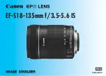
EF-S18-135mm f/3.5-5.6 IS STM
Brand: Canon Pages: 11
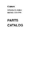
Speedlite 420EX
Brand: Canon Pages: 13
EF 70-200mm f/2.8L IS II USM
Brand: Canon Pages: 2
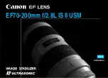
EF 70-200mm f/2.8L IS II USM
Brand: Canon Pages: 17
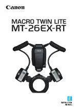
Macro Twin Light MT-26EX-RT
Brand: Canon Pages: 128
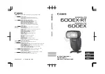
Speedlite 600EX-RT
Brand: Canon Pages: 372

EXPCMR-ALG-OZ-IC-1080PLE1-1227-250C-QD-15C-12.4
Brand: LARSON Pages: 4
EF-S10-18mm f/4.5-5.6 IS STM
Brand: Canon Pages: 16
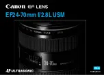
EF24-70mm f/2.8L USM
Brand: Canon Pages: 11

aw-he40 series
Brand: Panasonic Pages: 138

Apollo Marine 65 Series
Brand: Halma Pages: 2

W7
Brand: Wansview Pages: 12

BS-468/A
Brand: Olympia Pages: 62


