background image

www.acti.com


KCM-3211 Hardware Manual 


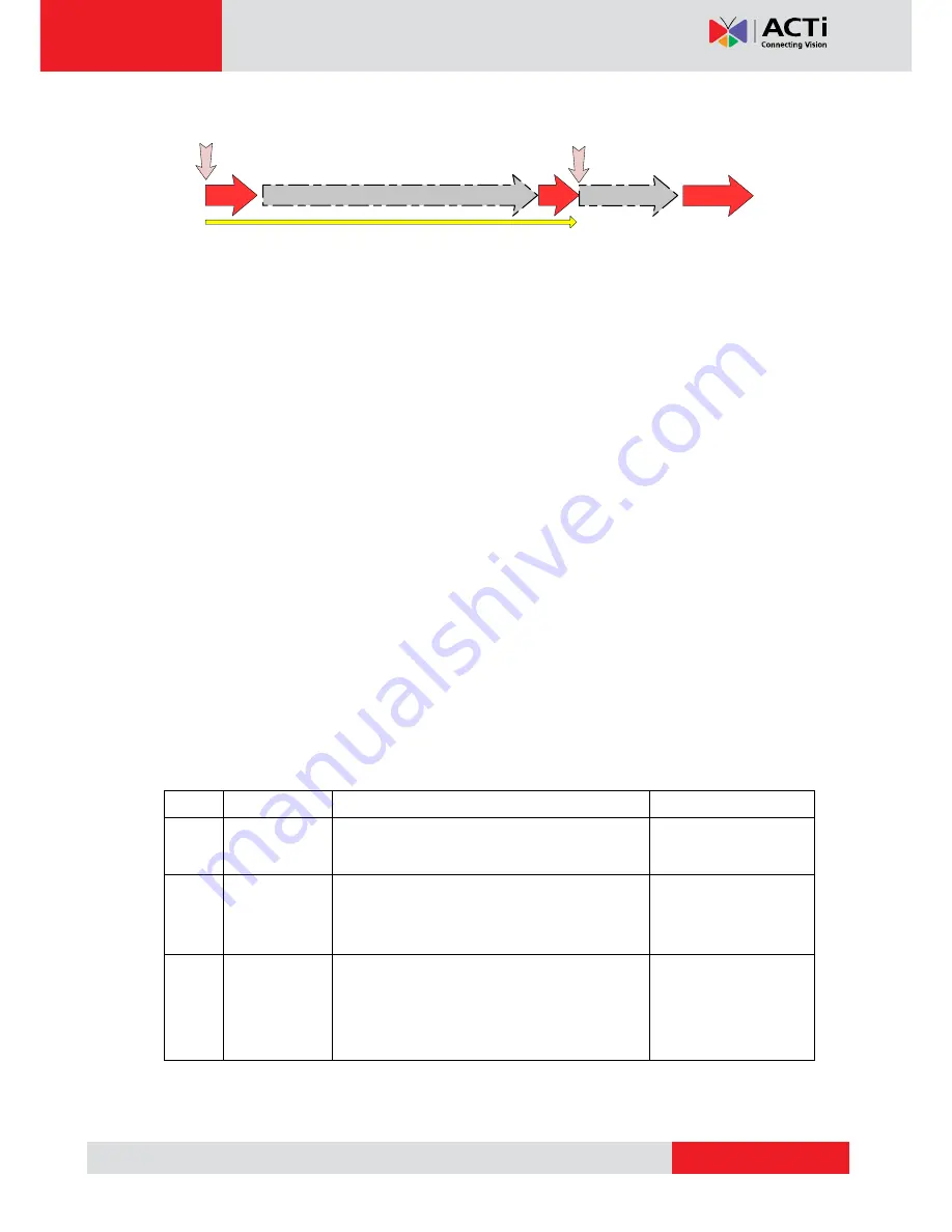
On (3s)

On 

1s

Power On

About 20 Seconds

Stay On

Off (about 15s)

Off (10~15s)

Restore to Default 

Complete


2)


Power Button 

Press the Power Button and then camera will reboot automatically. 


3)


Ethernet Port 

The IP device connects to the Ethernet via a standard RJ45 connector. Supporting NWAY, this 

IP device can auto detect the speed of local network segment (10Base-T/100Base-TX 

Ethernet). 


4)


Digital Input / Output 

Used in applications like motion detection, event triggering, time lapse recording, alarm 

notifications, etc., the I/O terminal connector provides the interface to:   


2 transistor output

 - For connecting external devices such as relays and LEDs. Connected 

devices can be activated by Output buttons on the Live View page or through video 

management software. Connect Pin 2 with 4 or 6 with 8. 


2 Digital Input

 - An alarm input for connecting devices that can toggle between an open and 

closed circuit, for example: PIRs, door/window contacts, glass break detectors, etc. The device 

will detect the change in digital input and transmit the signal to video surveillance servers.   


Pin 1 

GND 

Ground. Connect with Pin 3 for DI control loop.   

Pin 2 

12V   

Provides power to external devices with a 

maximum current of 100mA. 

Voltage: 12V DC, 

Max: 1.2W   

Pin 3 

Digital Input 

Connect to GND to activate, or leave floating 

(or unconnected) to deactivate. 

Must not be exposed 

to voltages greater 

than 30V DC.   

Pin 4 

Transistor 

Output 

Connect to Pin 2 through external devices for 

DO loop. If used with an external relay, a diode 

must be connected in parallel with the load for 

protection against transient voltages. 

Max load = <100mA 

Max voltage = 24V DC 

(to the transistor) 

(Pin 5 

– 8 repeats Pin 1-4 for another set of DIO) 

Connect input/output devices to the camera as follows:   

Summary of Contents for KCM-3211

Page 1: ...KCM 3211 3 6x Zoom H 264 4 Megapixel IP D N PoE Indoor Dome with P Iris DC 12V PoE Ver 2013 12 11...

Page 2: ...age Contents 4 Features and Benefits 5 Safety Instructions 6 Physical description 8 Installation Procedure 11 Surface Installation 11 Adjusting the Viewing Angle 13 Accessing Camera 15 If you have DHC...

Page 3: ...he writing of this manual Please inform your local office if you find any inaccuracies or omissions We cannot be held responsible for any typographical or technical errors and reserve the right to mak...

Page 4: ...www acti com KCM 3211 Hardware Manual 4 Introduction Package Contents KCM 3211 QIG Product CD Terminal Blocks for Power DI O and Audio Accessories Warranty Card Drill Template...

Page 5: ...dome shell protects against brute force impact It is extremely durable against any tampering intruder IP66 construction isolates electronics against the elements Rain sleet or snow nothing goes throu...

Page 6: ...er and Moisture Do not use this video product near water for example near a bathtub washbowl kitchen sink or laundry tub in a wet basement or near a swimming pool and the like Don t use accessories no...

Page 7: ...nstruction manual as an improper adjustment of other controls may result in damage and will often require extensive work by a qualified technician to restore the video product to its normal operation...

Page 8: ...p 3 Reconnect the power cable while continuing to hold the reset button The red Power LED light will flash on for 3 second first turn off for about 15 seconds flash on for another second and turn off...

Page 9: ...software Connect Pin 2 with 4 or 6 with 8 2 Digital Input An alarm input for connecting devices that can toggle between an open and closed circuit for example PIRs door window contacts glass break det...

Page 10: ...mera 5 DC 12V Power Input Connect DC power source to the terminal block The wire with white dashed lines is the live wire which should connect to the 12V pin 6 Micro SD Micro SDHC Card Slot Insert you...

Page 11: ...n the wall or the ceiling and directly install the camera on a surface To do this follow the procedures below 1 Drill the holes Using the supplied drill template in the camera package mark the holes o...

Page 12: ...e screws Since electric screwdrivers vary in sizes speed and force they may bruise and damage the internal camera components DISCLAIMER ACTi will not be responsible for camera damage caused by imprope...

Page 13: ...le Camera Parts Overview Adjustment Procedures 1 Loosen the tilt adjustment screws adjust the tilt and then tighten back the screws to fix the tilt position 2 Move the rotation adjustment to rotate th...

Page 14: ...rdware Manual 14 NOTE If you need to tighten or loosen the pan adjustment knob and adjustment by hand is not enough insert the bundled pan bracket wrench into the hole on the knob and then push it to...

Page 15: ...by changing your PC s IP address to the subnet with prefix 192 168 0 XXX The last number should be anything from 1 to 254 except 100 and other occupied IP addresses Subnet mask should be 255 555 255...

Page 16: ...t IP 192 168 0 100 5 When you see the login window please input default user and password Default User Admin Password 123456 6 After logging in you will see the video from camera To go to the main men...

Page 17: ...168 0 101 or any other unused IPs Do NOT use the PC s IP address or 192 168 0 100 If this is not the first device you add to the network please also avoid other devices IPs 10 Click Apply 11 Please g...

Reviews: