ACTi E89, Hardware Manual
The ACTi E89 hardware manual is a comprehensive guide to help you set up and optimize your security camera system. Download the free manual from manualshive.com to access detailed instructions and troubleshooting tips. Ensure smooth operation and maximize the potential of your ACTi E89 with this essential resource.
Share
Download


Reviews:
No comments
Related manuals for E89
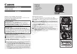
EF 24mm f/2.8 IS USM
Brand: Canon Pages: 2
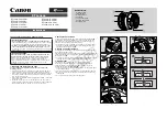
EF14mm f/2.8L II USM
Brand: Canon Pages: 2
EF24-105MM F/4L IS USM
Brand: Canon Pages: 21
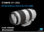
EF100-400mm f/4.5-5.6L IS II USM
Brand: Canon Pages: 21
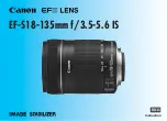
EF-S18-135mm f/3.5-5.6 IS STM
Brand: Canon Pages: 11
EF 70-200mm f/2.8L IS II USM
Brand: Canon Pages: 2
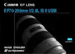
EF 70-200mm f/2.8L IS II USM
Brand: Canon Pages: 17
EF-S10-18mm f/4.5-5.6 IS STM
Brand: Canon Pages: 16
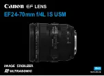
EF24-70mm f/2.8L USM
Brand: Canon Pages: 11

PowerShot G6
Brand: Canon Pages: 2

BC 50
Brand: Garmin Pages: 8

VIRB Elite
Brand: Garmin Pages: 6

BLK-IPS101
Brand: S/C Black Pages: 34

DP30BW
Brand: Olympus Pages: 31

A800S
Brand: 70mai Pages: 6

DASH VIEW 50
Brand: Uniden Pages: 28

PREMIUM INDOOR CAMERA
Brand: Frontpoint Pages: 9

CAMEDIA C-480 ZOOM
Brand: Olympus Pages: 100


