background image


220010439-G 


10


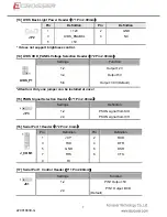
[27] SATA2 DOM Power Supply Selection Header (3*1 Pin 2.00mm) 

Settings 

Function 

1-2 

              Pin 7 Output

+5V   


J1


2-3 

     Pin 7 Output

GND 

Default


[28] VGA Header

12*1 Pin 2.00 mm

(Reserve for Test) 

Pin 

Definition 

Pin 

Definition 

1 CRT_ON 2  VSYNC 

3 HSYNC 4  GND 

5 RED 6 GND 

7 GREEN 8  GND 

9 BLUE 10 GND 


J_VGA1 

11 DDCDAT 12 DDCCLK 

Note. It can not use USB Hub with power adaptor that connects to USB port. 


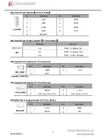
[29] Mini PCIe USB Signal Control Header

3*1 Pin 2.54 mm


Heade

Settings 

Definition 

J13 1-2 

J14 1-2 

USB signal supported (Default) 

J13 2-3 


J13

J14 

 J14 

2-3 

N/A 


Summary of Contents for AMB-D255T1

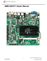
Page 1: ...220010439 G 1 AMB D255T1 Quick Manual...

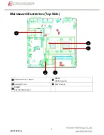
Page 2: ...220010439 G 2 Mainboard illustration Top Side Intel D2550 CPU 1 86GHz SATA 2 SATA Connector Intel NM10 PCH Mini PCIe slot DIMM 1 204 Pin DDR3 Socket 1 2 3 4 5...

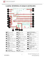
Page 3: ...Headers for front SPK and MIC JP3 Headers of PSON source selection SYS_FAN2 System Fan Connector J_GPIO1 Pin Header for GPIO J_COM1 Serial Port 1 Header SATA_P1 Pin Header for SATA Power F_USB2 Pin He...

Page 4: ...ble in accessory to avoid the System damage 03 CMOS Control Jumper 3 1Pin 2 54 mm Setting Instruction 1 2 Normal Default JCMOS1 2 3 Clear CMOS 04 Front Panel Header 5 2 Pin 2 54 mm Pin Definition Pin...

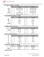
Page 5: ...Pin Definition Pin Definition 1 5 V 2 5 V 3 USBP4 4 USBP5 5 USBP4 6 USBP5 7 GND 8 GND F_USB2 10 N C 08 KBMS Header 6 1 Pin 2 0mm Pin Definition Pin Definition 1 KB_CK1 2 KB_DT1 3 MS_CK1 4 GND J_KBMS...

Page 6: ...22 GND 23 PE 24 GND J_LPT1 25 SLCT 26 N C 12 LVDS Header 15 2 Pin 2 0mm Pin Definition Pin Definition 1 LVDS_P1 2 LVDS_P1 3 LVDS_P1 4 NC 5 GND 6 GND 7 LVDS_A_DATA0_N 8 LVDS_A_DATA0_P 9 LVDS_A_DATA1_N...

Page 7: ...4 Output 5V LVDS_P1 5 6 Output 3 3V Default Attention Only one jumper can be installed at once 15 PSON Signal Selection Header 3 1 Pin 2 00mm Settings Definition 1 2 PSON signal from SIO JP3 2 3 PSON...

Page 8: ...Definition Pin Definition 1 JC3_P 2 JC3_TTL1 RXD 3 JC3_TTL2 TXD 4 DTR 5 GND 6 DSR 7 RTS 8 CTS J_COM3 9 N C or JC3_P Attention The Pin9 output default value is NC but it also can output 5V or 12V by ch...

Page 9: ...2 PIN1 9 Output 5V 2 3 PIN1 9 Output 12V JC4 3 4 PIN1 9 NC Default 24 System Fan1 Header 3 1 Pin 2 54 mm Pin Definition Pin Definition 1 GND 2 12V SYS_FAN1 3 N C Used for CPU Fan 25 System Fan2 Header...

Page 10: ...Reserve for Test Pin Definition Pin Definition 1 CRT_ON 2 VSYNC 3 HSYNC 4 GND 5 RED 6 GND 7 GREEN 8 GND 9 BLUE 10 GND J_VGA1 11 DDCDAT 12 DDCCLK Note It can not use USB Hub with power adaptor that con...

Reviews: