Acrosser Technology AIV-HM76V1FLCE1 User Manual Download Page 66

AIV-HM76V1FL Series User Manual

66

Acrosser Technology Co., Ltd.

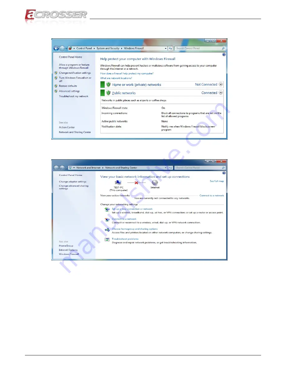
•  If the problem still exist, please shut down the firewall and anti-virus software.

•  If the Network Connections/Local Area Connection show “no connection”, please 

check your network cable connection.

Summary of Contents for AIV-HM76V1FLCE1

Page 1: ...ual User Manual Acrosser Technology Co Ltd www acrosser com AIV HM76V1FL Series An in vehicle computer designed for comprehensive mobile applications 3rd Generation Intel Core i7 i3 or Celeron Processor with Intel PCH HM76 Chipset ...

Page 2: ...ry information protected by copyright All rights are reserved No part of this manual may be reproduced by any mechanical electronic or other means in any form without prior written permission of Acrosser Technology Co Ltd Trademarks The product names appear in this manual are for identification purpose only The trademarks and product names or brand names appear in this manual are the property of t...

Page 3: ... Module Installation 17 2 6 WiFi Module Installation 18 2 7 Antenna Connection 19 2 8 Power Connection 19 2 9 Status HDD Power LED Display 20 2 10 Blade type Fuse Holder 21 3 BIOS Settings 22 3 1 Main Setup 22 3 2 Advanced Setup 24 3 2 1 SATA Configuration 24 3 2 2 USB Device 25 3 2 3 F81216 Second Super IO Configuration 26 3 2 4 W83627DHG HW Monitor 27 3 2 5 Power Sub System 28 3 3 Chipset Setup ...

Page 4: ...4 5 2 2 2 Watchdog 55 5 2 3 Power Subsystem 55 5 2 4 I Button 60 5 3 Appendix A 61 6 FAQ 62 Q 1 Why the Linux operating system can not re install by the same storage device 62 Q 2 Why the monitor display abnormally on screen during Linux installation 62 Q 3 Why the display resolution only for 800x600 and 1024x768 at X Window under Basic Graphics Mode 62 Q 4 Does my system support Windows 8 62 Q 5 ...

Page 5: ... HM76V1FLCi3 Intel Core i3 3217UE Processor 3M Cache 1 6GHz AIV HM76V1FLCE1 Intel Celeron 1047UE Processor 2M Cache 1 4GHz Chipset Intel HM76 Memory DDR3 1333 1600MHz support up to 16GB 2 x 204 pin SO DIMM sockets non ECC 2G 2G 4G 4G 8G 8G option BIOS Support SPI BIOS BIOS function Support SSID only for Acrosser user Graphic Controller Integrated within HM76 Display VGA COMBO Connector Analog RGB ...

Page 6: ...m 1M bps or user defined baud rate 3 Time stamp of CAN message 4 API library for user development 5 CAN bus device status query GPIO GPIO 4 in 4 out DB15 male Connector Input 1 4 input isolated channels 2 Max voltage 32V 3 Signal type A Open Ground switch input B Digital Logic Logic High 3V 32V Logic Low 0V 0 7V Maximum input frequency 10KHz duty 50 Output 1 4 channels 2 Output type Open drain MOS...

Page 7: ...r voltage protection Polarity reversed protection Input Connector 3 pin terminal block 5 08mm pitch Fuse Connector Blade type fuse holder Dimension 162 9 x 30 mm Software OS Support Windows 7 32 64 bit 7 Embedded 32 bit Fedora 17 32 64 bit Ubuntu 12 10 32 64 bit WatchDog Timer Software programmable 0 255 seconds 0 disable timer Mechanical Environment Thermal Design Fanless heatsink Chassis Sheetme...

Page 8: ... 1 x AIV HM76V1FL System AIV HM76V1FLCE1 AIV HM76V1FLCi3 or AIV HM76V1FLCi7 1 x Quick Guide 1 x Driver CD 1 x Screw Pack 2 5 HDD bracket 4pcs 1 x Terminal Block Female 3 pin For power input 1 x Spare Fuse 10A 1 x Remote Switch Cable 1 x One to many Video Combo Cable Combo to VGA USB Audio DC Cable 1 x GPIO CAN Driver ID Cable 1 3 Features Rugged fanless design Support Intel 3rd generation Core i3 ...

Page 9: ...AIV HM76V1FL Series User Manual 9 www acrosser com 1 4 System Dissection 1 4 1 Dimensions Unit mm ...

Page 10: ...AIV HM76V1FL Series User Manual 10 Acrosser Technology Co Ltd 1 4 2 I O Panel Front IO COM HDMI COMBO USB3 0 LAN Remote Power Input Rear I O WiFi 3G GPS Bluetooth Fuse GPIO ...

Page 11: ... 20 B2 B1 A2 A1 7 8 1 B2 B1 A2 A1 7 8 1 10 9 2 1 1 1 4 5 8 1 2 19 18 1 2 19 18 9 1 1 2 5 6 CCMOS1 GPIO1 PIC1 BT1 GPS1 PWR1 JP1 SATA1 CPIC1 PIC2 COM4 COM1 SATA_PWR1 COM2 COM3 USB2 USB1 HDMI2 HDMI1 LED1 USB3 LAN1 LAN2 COMBO1 REMOTE1 Bottom View 1 2 71 73 204 203 2 1 72 74 203 204 1 4 5 8 1 4 5 8 52 51 17 15 18 16 1 52 51 17 15 18 16 2 1 MINIPCIE2 MINIPCIE1 SW2 SW3 SIM1 CF1 ...

Page 12: ...AIV HM76V1FL Series User Manual 12 Acrosser Technology Co Ltd 1 4 4 Power Board Top View CN_12V1 CN_12V2 LED1 ...

Page 13: ...fingers Step 2 Pull out the disk tray and install your 2 5 SATA disk Step 3 Fasten the disk with 4 screws provided in the package Step 4 Firmly push the disk tray back into the disk compartment The disk is now connected with the system Step 5 Push in the disk tray and fasten the two disk tray screws by your screw driver or fingers Step 6 Complete ...

Page 14: ... screws by your screw driver Step 2 Pull out the card tray Loosen the two screws that locks the card holder Slide your CF card into the card holder Screw back the card holder Step 3 If there is no need to install the SIM card push in the card tray and fasten the two card tray screws by your screw driver Step 4 Complete ...

Page 15: ...ystem configuration Step 1 Leave the CF card tray on table Step 2 Use a clip to install your SIM card into the SIM1 slot on the mainboard Pay attention to its orientation and do not scratch the contacts Step 3 Push in the card tray and fasten the two card tray screws by your screw driver Step 4 Complete Note To remove the card first you have to push it in and then pull it out ...

Page 16: ...screw driver to remove the DIMM card cover plate located at the chassis bottom Step 2 Install your DIMM card into the CN_DIMM1 or CN_DIMM2 slot on the mainboard Pay attention to its orientation and do not scratch the contacts Step 3 Place back the DIMM card cover plate and have it fastened Step 4 Complete ...

Page 17: ...emove the cover plate located at the chassis bottom Step 2 Install your 3 5G module into the MINIPCIE1 slot on the mainboard Pay attention to its orientation and do not scratch the contacts Step 3 Attch the RF plug from the system to your module Step 4 Place back the cover plate and have it fastened Step 5 Complete ...

Page 18: ...to remove the cover plate located at the chassis bottom Step 2 Install your WiFi module into the MINIPCIE2 slot on the mainboard Pay attention to its orientation and do not scratch the contacts Step 3 Attch the RF plugs from the system to your module Step 4 Place back the cover plate and have it fastened Step 5 Complete ...

Page 19: ...Antenna Connection Connect your antenna needed according to your system configuration 2 8 Power Connection Connect your power cable 9V 32V DC input connector Terminal Block 3 pin Pitch 5 08mm Pin Signal V 9V 32V DC Power Input IGN Ignition On Hi Active V GND ...

Page 20: ... will have a 2 second OFF in between LED Flashing Numbers Status 0 Constant On Power output runs normally 1 Standby Mode System off 3 Power On Delay 5 Boot Up Delay 6 Soft Off Delay 4 Shutdown Delay 2 Hard Off Delay If abnormal condition occur the LED will flash a 1 5 second pulse followed by numbers of 200 ms pulse to indicate the error status LED Flashing Numbers Error Status 1 Long 1 Short Syst...

Page 21: ...ion Output 12V 100W Input 9V 32V 111W Efficiency 90 Car Battery Blade type fuse suggestion Remarks 12V System CONQUER ATQ 10 Voltage Rating 32V Current Rating 10A 24V System CONQUER ATQ 5 Voltage Rating 32V Current Rating 5A Note You may have to use a needle nose pliers to grip on the fuse and pull it out ...

Page 22: ...and then press the Enter key to select the item and configure the functions Aptio Setup Utility Copyright C 2012 American Megatrends Inc Version 2 15 1226 Copyright C 2012 American Megatrends Inc Select Screen Select Item Enter Select Change Opt F1 General Help F2 Previous Values F3 Optimized Defaults F4 Save Exit ESC Exit Main Advanced Chipset Boot Security Save Exit BIOS Information BIOS Vendor ...

Page 23: ...IOS Version Memory RC Version Total Memory Memory Frequency ME FW Version ME Firmware SKU System Language System Date System Time Access Level IvyBridge 1400 MHz 306a9 E1 2Core s 2Thread s 19 GT2 900 MHz 2143 1 5 0 0 4096 MB DDR3 1600 MHz 8 0 10 1464 1 5MB English Fri 05 23 2014 11 22 33 Administrator Set the Time Use Tab to switch between Time elements Note Listed at the bottom of the menu are th...

Page 24: ...16 Second Super IO Configuration W83627DHG HW Monitor Power Sub System SATA Device Options Settings 3 2 1 SATA Configuration SATA device options settings Aptio Setup Utility Copyright C 2012 American Megatrends Inc Version 2 15 1226 Copyright C 2012 American Megatrends Inc Select Screen Select Item Enter Select Change Opt F1 General Help F2 Previous Values F3 Optimized Defaults F4 Save Exit ESC Ex...

Page 25: ...ends Inc Select Screen Select Item Enter Select Change Opt F1 General Help F2 Previous Values F3 Optimized Defaults F4 Save Exit ESC Exit Advanced USB Device USB Devices 1 Keyboard 1 Mouse 2 Hubs Legacy USB Support Enabled Enable Legacy USB support AUTO option disables legacy support if no USB devices are connected DISABLE option will keep USB devices available only for EFI applicatipon Legacy USB...

Page 26: ...ect Item Enter Select Change Opt F1 General Help F2 Previous Values F3 Optimized Defaults F4 Save Exit ESC Exit Advanced F81216 Second Super IO Configuration F81216 Second Super IO Chip COM 1 Configuration COM 2 Configuration COM 3 Configuration COM 4 Configuration COM4 422 485 function F81216 SecondIO RS 422 Set Parameters of COM 1 COM 1 COM 4 Configuration This option sets the parameters of COM1...

Page 27: ...us Values F3 Optimized Defaults F4 Save Exit ESC Exit Advanced F8121PC Health Status SYSTIN temperature CPUTIN temperature VCORE 5V 12V 3 3V VBAT 41 C 51 C 0 840 V 5 150 V 11 880 V 3 440 V 3 280 V SYSTIN temperature This item displays the system temperature CPUTIN temperature This item displays the CPU temperature 5V This item displays the 5V voltage level 12V This item displays the 12V voltage le...

Page 28: ...M76V1 V1 0 In Vehicle 11 62 V Disabled 1 5 V Disabled 8 5 180 60 Enabled Disabled Battery Low Voltage Monitor Function Power Board Type Options Description In Vehicle Embedded Displays the power board type Battery Voltage Detects and display the battery voltage level Note The following items apper only if the Power Board Type is In Vehicle Battery Low Monitor Options Description Enabled Disabled E...

Page 29: ...fore all power off 3 3 Chipset Setup Aptio Setup Utility Copyright C 2012 American Megatrends Inc Version 2 15 1226 Copyright C 2012 American Megatrends Inc Select Screen Select Item Enter Select Change Opt F1 General Help F2 Previous Values F3 Optimized Defaults F4 Save Exit ESC Exit Main Advanced Chipset Boot Security Save Exit Lan 1 LAN 1 ASPM Lan 2 LAN 2 ASPM Audio SB USB Configuration Graphic...

Page 30: ...Configuration Aptio Setup Utility Copyright C 2012 American Megatrends Inc Version 2 15 1226 Copyright C 2012 American Megatrends Inc Select Screen Select Item Enter Select Change Opt F1 General Help F2 Previous Values F3 Optimized Defaults F4 Save Exit ESC Exit Chipset SB USB Configuration xHCI Mode EHCI1 EHCI2 Mode of operation of xHCI controller Auto Enabled Enabled xHCI Mode Options Descriptio...

Page 31: ...e Internal Graphics Device IvyBridge 1 5 0 0 Unsupported 64M 256M VBIOS Default DVMT Pre Allocated Options Description 32M 64M 96M 128M 160M 192M 224M 256M 288M 320M 352M 384M 416M 448M 480M 512M 1024M Select DVMT 5 0 Pre Allocated Fixed Graphics Memory size used by the Internal Graphics Device DVMT Total Gfx Mem Options Description 128M 256M MAX Select DVMT 5 0 Total Graphics Memory size used by ...

Page 32: ... Boot Option Priorities Number of seconds to wait for setup activation key 65535 0xFFFF means indefinite waiting 2 On Enabled 07 69 Setup Prompt Timeout Options Description N A The number of seconds to wait for setup activation key 65535 0xFFFF means indefinite waiting Bootup NumLock State Options Description On Off Select the keyboard NumLock state Boot Logo Options Description Enabled Disabled E...

Page 33: ...cription If ONLY the Administrator s password is set then this only limits access to Setup and is only asked for when entering Setup If ONLY the User s password is set then this is a power on password and must be entered to boot or enter Setup In Setup the User will have Administrator rights The password length must be in the following range Minimum length Maximum length Administrator Password Sys...

Page 34: ...Save Changes Discard Changes Restore Defaults Save as User Defaults Restore User Defaults Boot Override Save Changes and Exit Exit system setup after saving the changes Discard Changes and Exit Exit system setup without saving any changes Save Options Save the options that have been made so far Save Changes Save Changes done so far to any of the setup options Discard Changes Discard Changes done s...

Page 35: ...led with all the drivers utilities applications and documents this product may need Put the Driver CD into your CD ROM drive The Driver CD will automatically detect the mainboard information to see if they are matched The following error messages appear if you use an incorrect Driver CD version with your mainboard Please find the correct Driver CD to proceed ...

Page 36: ...anual 36 Acrosser Technology Co Ltd Put the correct Driver CD of your mainboard into your CD ROM drive The following installation screen should appear If not enter the root folder of the Driver CD run the excution file Setup exe ...

Page 37: ...allation Page Step 1 Select the Driver tab Click the Select All button to select all the driver checkboxes and then click Install button to start installing all the selected drivers Step 2 The driver installation completeed The configuration will be valid after reboot ...

Page 38: ...ing the utility you should install Driver to initiate peripherals e g GPIO and WatchDog This Test Utility can be used to verify both system GPIO and WatchDog features Note To run the Testing Utility completely you should do it at test signed kernel mode under Windows 7 x64 by the command BCDEdit set testsigning on For more information please refer to MSDN by the following URL http msdn microsoft c...

Page 39: ...AIV HM76V1FL Series User Manual 39 www acrosser com Step 2 The Test Utility screen appears Select 1 GPIO Utility Select 2 WatchDog Utility ...

Page 40: ...AIV HM76V1FL Series User Manual 40 Acrosser Technology Co Ltd Select 3 Power Subsystem Select 4 Can Bus Select 5 I Button ...

Page 41: ...anual 41 www acrosser com 4 4 Application Installation Page Step 1 Select the Application tab Click the Acrobat Reader box Step 2 Please install Acrobat Reader This application is needed for reading the User Manual in PDF format ...

Page 42: ...er Technology Co Ltd Step 3 Please install Intel_MEI and Acrosser Driver into the system Windows OS will create AcroDev device Step 4 If the Windows Security warning message appears select Install this driver software anyway to go on next step ...

Page 43: ...AIV HM76V1FL Series User Manual 43 www acrosser com Step 5 Install Drivers for Optional Modules ...

Page 44: ... Manual 44 Acrosser Technology Co Ltd 4 5 Document Page The user manual is stored in the Document folder Note To read the PDF file you will have to install Acrobat Reader first Please refer to the Application Installation Page ...

Page 45: ...e the CAN packages via the CAN bus hardware interface 4 Set the CAN package filter to selectively receive CAN packages with specific ID 5 Set the mask bits to selectively make some filter bits take effect In the folder HM76V1FL Utility on the CD we provide 1 API header file 2 API library in static library format and shared library format 3 Test utility 5 1 1 2 CAN Message Format TYPE DEFINITION ty...

Page 46: ... Frame CAN packet the bit 0 bit 10 in the id field is the ID of the CAN packet The bit 11 bit 31 are ignored when the APIs in the library processing the CanMsg variable If a CanMsg variable is configured as an Extended Data Frame CAN packet the bit 0 bit 28 in the id field is the ID of the CAN packet The bit 29 bit 31 are ignored when the APIs in the library processing the CanMsg variable id_type ...

Page 47: ...s open the device node dev AcroDev implicitly so acquiring a file descriptor of dev AcroDev is not ncecssary On Windows platform after successfully installing the device driver there is a device which shows Acrosser Device in the Device Manager The APIs on Windows platform open this device implicitly 5 1 3 Power Subsystem 5 1 3 1 Overview The Power Subsystem APIs can be used to get and set the con...

Page 48: ...on Windows platform to support COM ports 5 1 4 I Button Function In the API library we provide a set of I Button functions Users can use the functions to 1 Reset the I Button 2 Read data from the I Button 3 Write data to the I Button 5 2 API List and Descriptions 5 2 1 CAN Bus Syntax i32 getCanFwVer PicInfo ver Description This function gets the version information of the CAN Bus firmware Paramete...

Page 49: ...ne BAUD_RATE_800K 8 define BAUD_RATE_1000K 9 Parameters This function gets a number which represents the specific Baud Rate and stores it at the memory which is pointed at by the pointer baud Return Value If this function gets the baud rate successfully it returns 0 any other returned value stands for error Syntax i32 setCanBaudRate u8 baud Description This function sets the Baud Rate of the CAN B...

Page 50: ...ackets in the canAry over the CAN bus unsigned int result 0 struct CanMsg canAry 30 Initialize the CAN packages in the canAry 30 result sendCanMessages canAry 30 if result 0 fprintf stderr Send CAN package error n Syntax i32 getCanMessage struct CanMsg buffer u8 count Description This function receives CAN packets from the CAN bus subsystem Parameters This function stores received CAN packages seq...

Page 51: ...th table Mask bit n Filter bit n Message ID bit n Accept or reject bit n 0 x x Accept 1 0 0 Accept 1 0 1 Reject 1 1 0 Reject 1 1 1 Accept Note x don t care Parameters This parameter mask is a pointer to a variable of type CanMask Users use the field maskId to indicate the mask they want and the API put the setting of the mask in the mask field struct CanMask u8 maskId 0 or 1 u32 mask Return Value ...

Page 52: ...urn Value If this function sets the mask setting successfully it returns 0 any other returned value stands for error Syntax i32 getCanFilter struct CanFilter varFilter Description This function gets the current setting of the acceptance filter Use the filterId field in a CanFilter variable to indicate the filter you want and the API puts the setting of the indicated filter in the filter field in t...

Page 53: ...ype CanFilter as the parameter Users set up the filterId There are six filters so the filterId could be 0 5 Filter0 and filter1 are associated with mask0 Filter2 filter5 are associated with mask1 By setting up filterType users indicate the type of the filter Filter type could be STD_ID or EXT_ID Depending on the filter type the filter field in the CanFilter variable could be 0x0 0x7FF 11 bits when...

Page 54: ...2 result result getChLevel val if result 0 printf Fail to get GPIO status n Return Value If the function gets the value successfully it returns 0 any other returned value stands for error Syntax i32 setChLevel u8 val Description Set the status of GPIO Output pins Parameters This function takes an unsigned char as the parameter The bit0 bit3 in variable val represent the status of the output pins T...

Page 55: ... and starts to count down The value could be 0 255 The unit is second Setting the timer register to 0 disables the watchdog function and stops the countdown Parameters The parameter val is the value to set to watchdog timer register The range is 0 255 Return Value None 5 2 3 Power Subsystem Syntax i32 getPwrFwVer struct PicInfo ver Description This function gets the version information of the firm...

Page 56: ...rn 0 any other value standards for error Syntax i32 getRemoteSwitch u8 val Description The function gets the status of the Remote Switch Parameters This function takes a pointer to an unsigned char variable as the parameter After calling this function the status of the Remote Switch will be put at the memory which is pointed by the parameter val If the Remote Switch is enabled val is 0x5A If the R...

Page 57: ...rns 0 any other value standards for error Syntax i32 getBattMonitor u8 val Description The function gets the status of the Battery Monitor Parameters This function takes a pointer to an unsigned char variable as the parameter After calling this function the status of the Battery Monitor will be put at the memory which is pointed by the parameter val If the Battery Monitor is enabled val is 0x5A If...

Page 58: ...e parameter Return Value If this function works successfully it returns 0 any other value standards for error Syntax i32 setSoftOffDelay u32 setTime Description The Soft Off Delay is the interval between that the system receives a power off signal and that the system generates a power off signal This function sets up the interval in seconds Parameters The parameter is of the type of unsigned long ...

Page 59: ...eters The parameter is a pointer which points to an unsigned long variable The returned value is stored at this variable The unit of the returned value is in seconds Return Value If this function works successfully the function returns 0 any other value stands for error Syntax i32 getPowerOnDelay u32 val Description This function gets the Power On delay Parameters This function takes a pointer to ...

Page 60: ...for error 5 2 4 I Button Syntax i32 resetIbutt void Description This function resets the I Button Parameters None Return Value If this function works successfully the function returns 0 any other value stands for error Syntax i32 readIbutt u8 data Description This function reads data from the I Button Parameters This function takes a pointer to an unsigned char variable The data to be read from th...

Page 61: ...vi boot grub grub conf default 0 timeout 5 splashimage hd0 0 grub splash xpm gz hiddenmenu title Fedora Core 2 6 27 5 117 FC10 root hd0 0 kernel vmlinuz 2 6 27 5 117 FC10 ro root dev hda2 rhgb quiet 8250 nr_uarts 6 noirqdebug initrd initrd 2 6 27 5 117 FC10 img 2 List the status of the COM ports in the system setserial g dev ttyS dev ttyS0 UART 16550A Port 0x03f8 IRQ 4 dev ttyS1 UART 16550A Port 0...

Page 62: ...d Min for both horizontal scanning and vertical scanning your monitor supported For example HorizSync 30 0 80 VertRefresh 50 75 Add the frequencies in XORG CONF for that vesa device and monitor Reboot system Q 4 Does my system support Windows 8 The system is designed and verified with Windows 7 Fedora 17 and Ubuntu 12 10 Acrosser did not verify this system with Windows 8 Please contact Acrosser lo...

Page 63: ... still exist please contact Acrosser FAE or authorized sales channels Q 7 Where is the serial number located on my system The serial number S N is an alpha numeric character located on the bottom or side chassis for reference only Q 8 How do I connect the second monitors to my system Basically there are duplicate and extend mode for the second monitor duplicate mode you will see the same contents ...

Page 64: ...board audio function in BIOS menu Make sure the audio driver and device was installed successfully Make sure the speaker is connected to the correct connector Check if the audio function is set to MUTE Please adjust the audio volume louder If the problem still exist please contact Acrosser FAE or authorized sales channels ...

Page 65: ...an be recognized in Device Manager If there is question mark or exclamation mark in the network adapter please re install the network driver If the problem still exist please contact Acrosser FAE or sales representative for testing Make sure the Network Connections Local Area Connection is enabled right click and choose Enable ...

Page 66: ...anual 66 Acrosser Technology Co Ltd If the problem still exist please shut down the firewall and anti virus software If the Network Connections Local Area Connection show no connection please check your network cable connection ...

Page 67: ... configuration or ISP WAN setting limitation Q 11 Why my optional module 3 5G connection fail in Fedora 17 x86 x64 system Although there is no need to install driver for 3 5G optional module in Fedora 17 x86 x64 system the following procedure need to be performed to ensure a successful connection 1 Enter terminal 2 Use root 3 gedit etc modprobe d blacklist conf 4 add blacklist sierra 5 poweroff 6 ...

Page 68: ...our E Mail Address Your Company Address Acrosser Model Name Acrosser Serial Number Describe System Configuration CPU Type Memory Size Storage Device e g HDD CF or SSD Additional Peripherals e g Graphic Card Operating System Version e g Windows 7 Embedded Special API or Driver If yes please provide it for debug Running Applications Others Describe Your Problems or Questions Send the above informati...

Page 69: ...o 21 Tai Ran 9th Rd Che Gong Miao Futian Dist Shenzhen China Postal 518040 TEL 86 755 83542210 FAX 86 755 83700087 Acrosser Shanghai Office 欣扬通电子有限公司 上海分公司 上海市徐汇区零陵路631号爱乐大厦12E 邮编 200085 12E Aile Building No 631 Ling ling Road Xu Hui Dist Shanghai China Postal 200085 TEL 86 21 64288853 FAX 86 21 64288854 Acrosser Beijing Office 欣扬通电子有限公司 北京分公司 北京市海淀区安宁庄西三条9号 宜品上层2 703 邮编 100085 Room 2 703 Yipinsha...

Reviews: