


ACS-B1086 User’s Guide
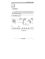
ACS-B1086
16
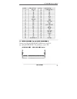
IDE4 PIN
DESCRIPTION
IDE3 PIN
DESCRIPTION
1
+5V
2
GND
3 +5V 4 GND
5
+5V
6
GND
7 +5V 8 GND
9 HDD_LED
10
DCD_CONSOLE
11 LAN1_ACT_LED
12 DSR_CONSOLE
13 LAN1_SPD_LED
14 RX_CONSOLE
15 LAN2_ACT_LED
16 RTS_CONSOLE
17 LAN2_SPD_LED
18 TX_CONSOLE
19 LAN3_ACT_LED
20 CTS_CONSOLE
21 LAN3_LINK_LED
22 DTR_CONSOLE
23 LAN4_ACT_LED
24 RI_CONSOLE
25 LAN4_LINK_LED
26
NC
27 LAN5_ACT_LED
28
NC
29 LAN5_LINK_LED
30
NC
31 LAN6_ACT_LED
32
NC
33 LAN6_LINK_LED
34 LAN2_LINK_LED
35 USB_5V 36
LAN1_LINK_LED
37 USB0- 38
COM1_RX_LED
39 USB0+ 40
COM1_TX_LED
41 USB1- 42
COM2_RX_LED
43 USB1+ 44
COM2_TX_LED
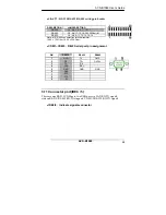
IDE5 PIN
DESCRIPTION
IDE4 PIN
DESCRIPTION
1
COM3_TX_LED
2
COM3_RX_LED
3 COM4_TX_LED
4 COM4_RX_LED
5
COM5_TX_LED
6
COM5_RX_LED
7 COM6_TX_LED
8 COM6_RX_LED
9 COM7_TX_LED
10 COM7_RX_LED
11 COM8_TX_LED
12 COM8_RX_LED
13 COM9_TX_LED
14 COM9_RX_LED
15 COM10_TX_LED
16 COM10_RX_LED
17 COM11_TX_LED
18 COM11_RX_LED
19 COM12_TX_LED
20 COM12_RX_LED
21 COM13_TX_LED
22 COM13_RX_LED
23 COM14_TX_LED
24 COM14_RX_LED
25 COM15_TX_LED
26 COM15_RX_LED
27 COM16_TX_LED
28 COM16_RX_LED
29 COM17_TX_LED
30 COM17_RX_LED
31 COM18_TX_LED
32 COM18_RX_LED
33 COM19_TX_LED
34 COM19_RX_LED
35 COM20_TX_LED
36 COM20_RX_LED
37 COM21_TX_LED
38 COM21_RX_LED
39 COM22_TX_LED
40 COM22_RX_LED
41 COM23_TX_LED
42 COM23_RX_LED
43 COM24_TX_LED
44 COM24_RX_LED


