SERIES IP503 INDUSTRIAL I/O PACK EIA/TIA-232E & CENTRONICS COMMUNICATION MODULE
___________________________________________________________________________________________
- 13 -
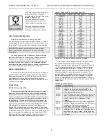
LPC - Line-Printer Control Register
LPC Bit
FUNCTION/PORT SIGNAL
0
STB - Printer-Strobe Control Bit
0 = Signal Negated
1= The Active Low Strobe Signal STB* is
asserted on the printer interface
1
AFD - Auto-Feed Control Bit
0 = Signal Negated
1 = The Active Low Auto-Feed Signal AFD* is
asserted on the printer interface
2
INIT - Initialize Printer Control Bit
0 = The Active Low INIT* is asserted on the
printer interface
1 = Signal Negated
3
SLIN - Select Input Control Bit
0 = Signal Negated
1 = The Active Low SLIN* signal pin is asserted
on the printer interface
4
INTREQ EN - Interrupt Request Enable
0 = Disables interrupts from the printer port
1 = Enables interrupts from the printer port
whenever the ACKN* signal is released
5
DIR - Direction Control Bit (used only when the
LEM register Extended Mode Bit is set to 1)
1 = Disables the output buffers of the printer port,
allowing data driven by external sources to be
read from the port
0 = The printer port is in the output (write) mode
6,7
Reserved (Reads as zero)
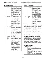
LEM - Line Printer Extended Mode Select (Read/Write)
Bit 0 of this register allows the printer enhanced mode to be
selected. This bit drives the PEMD line of the UART and is set
low (not asserted) following a reset. Programming this bit low
enables the connection between the Line Printer Data Register
(Write) and the parallel data lines (default mode of
operation)Setting this bit high selects the Extended Mode of
operation which allows direction control of the parallel data lines
using the direction control bit of the Line Printer Control Register
(LPC)The following table summarizes the action of the extended
mode bit and the direction control bit of the LPC register with
respect to the parallel data lines:
LEM BIT 0/PEMD
DIRECTIO
N
PARALLEL DATA LINES
L
X
PC/AT Mode - OUTPUT
H
0
PS/2 Mode - OUTPUT
H
1
PS/2 Mode - INPUT
In Extended Mode, read operations return either the last data
written to the port (if direction bit of LPC register is set to write/0),
or the data that is present in the port (if direction bit is set to
read/1)
Bits 1-7 of this register are not used and pullups on the
carrier board data bus will cause these bits to always read high.
After power-up or a system reset, this bit is cleared (bit 0 = 0) and
normal write-only operation is assumed
LIM - Line Printer Interrupt Mode Select (Read/Write)
This register allows selection of the parallel port interrupt
source (the ACKN line of the parallel port or bit 2 of the LPS
register)The serial ports and the parallel port interrupts drive
INTREQ0*Bit 0 of this register drives the ENIRQ* line of the
UART and is set high (not asserted) following a reset
Setting bit 0 of this register low enables the AT Mode of
interrupts. In the AT mode, INTREQ0* will bedriven by the
ACKN* input line of the parallel port. Setting LIM bit 0 high
selects the PS-2 Mode of interrupts (default mode)In PS-2 Mode,
INTREQ0* is driven by the PRINT* bit of the Line-Printer Status
Register (LPS bit 2)INTREQ0* is latched low on the rising edge of
the ACKN* parallel port signal. Then INTREQ0* is held low until
the Line Printer Status Register is read, which resets the PRINT*
status bit and INTREQ0* high
LIV - Line Printer Interrupt Vector Register (R/W)
This 8-bit read/write register operates the same as the serial
port SCR register and is used to store the interrupt vector for the
parallel port. In response to an interrupt select cycle, the IP
module will execute a read of this register for a parallel port
interrupt (see Interrupt Generation section for more details) After
power-up or a system reset, this register is cleared
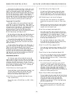
IP Identification PROM - (Read Only, 32 Odd-Byte Addresses)
Each IP module contains an identification (ID) PROM that
resides in the ID space per the IP module specification. This
area of memory contains 32 bytes of information at most. Both
fixed and variable information may be present within the ID
PROM. Fixed information includes the "IPAC" identifier, model
number, and manufacturer's identification codes. Variable
information includes unique information required for the module.
The IP503 ID PROM does not contain any variable (e.g. unique
calibration) information. ID PROM bytes are addressed using
only the odd addresses in a 64 byte block (on the “Big Endian”
VMEbus)Even addresses are used on the “Little Endian” PC bus.
The IP503 ID PROM contents are shown in Table 32Note that the
base-address for the IP module ID space (see your carrier board
instructions) must be added to the addresses shown to properly
access the ID PROM. Execution of an ID PROM Read requires 1
wait state
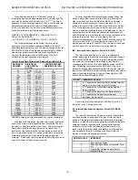
Table 32: IP503 ID Space Identification (ID) PROM
Hex Offset
From ID
PROM Base
Address
ASCII
Character
Equivalen
t
Numeric
Value
(Hex)
Field Description
01
I
49
All IP's have
'IPAC'
03
P
50
05
A
41
07
C
43
09
A3
Acromag ID Code
0B
07
IP Model Code
1
0D
00
Not Used
(Revision)
0F
00
Reserved
11
00
Not Used (Driver
ID Low Byte)
13
00
Not Used (Driver
ID High Byte)
15
0C
Total Number of
ID PROM Bytes
17
04
CRC
19 to 3F
yy
Not Used
Notes (Table 32):
1 The IP model number is represented by a two-digit code within
the ID PROM (the IP503 model is represented by 07 Hex)


