


Series AVME9125 VMEbus 6U Analog Input Board
___________________________________________________________________________________________
- 11 -
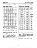
Mail Box Buffer (Read Only, 60H - 9EH)
The Mail Box Buffer is read-only, and contains 16-bit digitized
input channel values. The Mail Box Buffer has 32 storage
locations-one for each of the 32 channels supported. See Table
3.1 which gives the Mail Box Buffer address locations
corresponding to each of the 32 channels.
The New Data register can be read to determine which Mail
Box Buffers contain updated digitized data. A set bit in the New
Data register indicates an updated digitized data value resides in
its corresponding Mail Box Buffer. In addition, the Missed Data
register can be read to determine if a Mail Box Buffer has been
overwritten with a new digitized value before the previous one had
been read. A set bit in the Missed Data register indicates that a
digitized data value has been overwritten.
A read access to the Mail Box Buffer could take up to an extra
625n seconds if a read is issued while a hardware write to the
same Mail Box is currently underway. Holding off the data read of
the Mail Box prevents contention which could result in the writing
of erroneous data to the Mail Box.
MODES OF OPERATION
The AVME9125 provides four different modes of analog input
acquisition to give the user maximum flexibility for each
application. These modes of operation include: uniform
continuous, uniform single, burst continuous, and burst single. In
all modes a single channel or a sequence of channels may be
converted. The following sections describe the features of each
and how to best use them.
Uniform Continuous-Mode
In uniform continuous mode of operation, conversions are
performed continuously (in sequential order) for all channels
between and including the Start and End Channel Values. The
interval between conversions is controlled by the interval timer
(Timer Prescaler and Conversion Timer as described in the
Conversion Timer Register section). The interval timer must be
used in this mode of operation.
After software selection of the uniform continuous mode of
operation, conversions are started either by an external trigger, or
by setting the software start convert bit.
Stopping the execution of uniform continuous conversions is
possible by writing 000 to the Scan Mode bits (8-10) of the Control
register. See the Control register section for additional information
on the Scan Mode control bits and the Control register address
location.
Interrupts can be enabled to activate after conversion of each
channel or the group of channels defined by the Start and End
Channel Values. If interrupts are configured to go active after the
conversion of each channel, the actual interrupt will be issued
10.5
µ
seconds after the programmed interval has lapsed. If
interrupt upon completion of a group of channels is selected, an
interrupt will be issued 10.5
µ
seconds after the interval time of the
last selected channel has expired.
If interrupts are selected to go active after conversion of each
channel be sure to program a large enough interval between
conversions to allow adequate time for execution of an interrupt
service routine. It may also be necessary to allow time for your
computer to perform other housekeeping operations between
servicing interrupts.
Uniform Single-Mode
In uniform single mode of operation, conversions are
performed once (in sequential order) for all channels between and
including the Start and End Channel Values. After the channels
defined by the End Channel Value are converted conversions are
halted.
The interval between conversions of each channel is
controlled by the interval timer (Timer Prescaler and Conversion
Timer as described in the Conversion Timer Register section).
The interval timer must be used in this mode of operation.
After software selection of the uniform single mode of
operation, conversions are started either by an external trigger, or
by setting the software start convert bit.
Interrupts can be enabled to activate after conversion of each
channel or the group of channels as defined by the Start and End
Channel Values. If interrupts are configured to go active after the
conversion of each channel, the actual interrupt will be issued
10.5
µ
seconds after the programmed interval has lapsed. If
interrupt upon completion of a group of channels is selected, an
interrupt will be issued 10.5
µ
seconds after the interval time of the
last selected channel has expired.
Burst Continuous-Mode
In burst continuous mode of operation, conversions are
continuously performed in sequential order from the channel
defined by the Start Channel Value to the channel defined by the
End Channel Value. Within a group of channels, the interval
between conversions is fixed at
≅
15
µ
seconds. However, the
interval after conversion of a group of channels can be controlled
by the interval timer (Timer Prescaler and Conversion Timer).
Burst modes can be used to provide pseudo-simultaneous
sampling for many low to medium speed applications requiring
simultaneous channel acquisition. The 15
µ
seconds between
conversion can essentially be considered simultaneous sampling
for low to medium frequency applications.
After software selection of the burst continuous mode of
operation, conversions are started either by an external trigger, or
by setting the software start convert bit.
Stopping the execution of burst continuous conversions is
accomplished by writing 000 to the Scan Mode bits (8-10) of the
Control register. See the Control register section for additional
information on the Scan Mode control bits and the Control register
address location.
Artisan Technology Group - Quality Instrumentation ... Guaranteed | (888) 88-SOURCE | www.artisantg.com


