SERIES AP470 ACROPACK
USER
’S MANUAL
Acromag, Inc. Tel: 248-295-0310
- 30 -
http://www.acromag.com
- 30 -
www.acromag.com
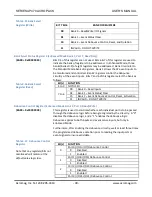
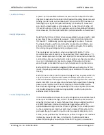
Table 3.15 Bank Select
Register (Write)
BIT 7 Bit 6
BANK OF REGISTERS
00
Bank 0 – Read/Write I/O Signals
01
Bank 1 – Event Status/Clear
10
Bank 2 – Event Debounce Control, Reset, and Duration
11
INVALID – DO NOT WRITE
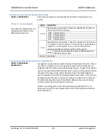
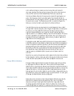
Bank Select Status Register 1 (Enhanced Mode Bank 1, Port 7, Read Only)
(BAR0 + 0x0000 0024)
Bits 0-5 of this register are not used. Bits 6 & 7 of this register are used to
indicate the bank of registers to be addressed. In Enhanced Mode, three
banks (banks 0-2) of eight registers may be addressed. Bank 0 is similar to
the Standard Mode bank of registers. Bank 1 allows the 32 event inputs to
be monitored and controlled. Bank 2 registers control the debounce
circuitry of the event inputs. Bits 7 and 6 of this register select the bank as
follows:
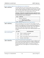
Table 3.16 Bank Select
Register (Read)
Bit(s)
FUNCTION
5 to 0
NOT USED
7 to 6
00
Bank 0 – Read Inputs
01
Bank 1 – Event Status/Clear
10
Bank 2 – Event Debounce Control, Reset, & Duration
11
INVALID – DO NOT WRITE
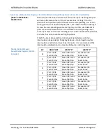
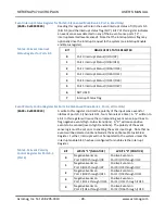
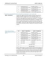
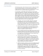
Debounce Control Register (Enhanced Mode Bank 2, Port 0, Read/Write)
(BAR0 + 0x0000 0008)
This register is used to control whether each individual port is to be passed
through the debounce logic before being recognized by the circuitry. A “0”
disables the debounce logic, and a “1” enables the debounce logic.
Debounce applies to both inputs and event sense inputs, but only in
Enhanced Mode.
Furthermore, after enabling the debounce circuitry, wait at least three times
the programmed debounce duration prior to reading the input ports or
event signals to insure valid data.
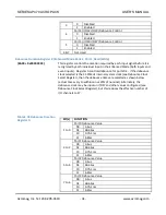
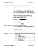
Table 3.17 Debounce Control
Register
Note that any registers/bits not
mentioned will remain at the
default value logic low.
Bit(s)
FUNCTION
0
Port 0 (I/O0-I/O7) Debounce Control
0
Disabled
1
Enabled
1
Port 1 (I/O8-I/O15) Debounce Control
0
Disabled
1
Enabled
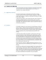
2
Port 2 (I/O16-I/O23) Debounce Control
0
Disabled
1
Enabled
Port 3 (I/O24-I/O31) Debounce Control


