SERIES AP440 ACROPACK
USER
’S MANUAL
Acromag, Inc. Tel: 248-295-0310
- 27 - http://www.acromag.com
- 27 -
www.acromag.com
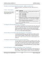
reported to the system unless the Interrupt enable bit-0 has been
configured for enable via the Interrupt Register.
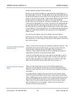
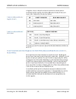
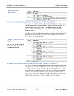
Table 3.14 Standard Mode
Events Register (Port 7)
BIT
WRITE “1” (NEGATIVE)
WRITE “0” (POSITIVE)
0
Negative Events on
Port 0 IN00 through IN03
Positive Events on
Port 0 IN00 through IN03
1
Negative Events on
Port 0 IN04 through IN07
Positive Events on
Port 0 IN04 through IN07
2
Negative Events on
Port 1 IN08 through IN11
Positive Events on
Port 1 IN08 through IN11
3
Negative Events on
Port 1 IN12 through IN15
Positive Events on
Port 1 IN12 through IN15
4
Negative Events on
Port 2 IN16 through IN19
Positive Events on
Port 2 IN16 through IN19
5
Negative Events on
Port 2 IN20 through IN23
Positive Events on
Port 2 IN20 through IN23
6
Negative Events on
Port 3 IN24 through IN27
Positive Events on
Port 3 IN24 through IN27
7
Negative Events on
Port 3 IN28 through IN31
Positive Events on
Port 3 IN28 through IN31
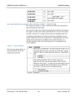
Bank Select Register (Enhanced Mode Bank 1, Port 7, Write Only)
Bits 6 & 7 of this register are used to select/monitor the bank of registers to
be addressed. In Enhanced Mode, three banks (banks 0-2) of eight registers
may be addressed. Bank 0 is similar to the Standard Mode bank of registers.
Bank 1 allows the 32 event inputs to be monitored and controlled. Bank 2
registers control the debounce circuitry of the event inputs. Bits 0-5 of this
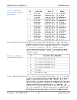
register are not used. Bits 7 and 6 select the bank as follows:
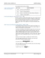
Table 3.15 Bank Select
Register (Write)
Bit(s)
FUNCTION
5 to 0
NOT USED
7 to 6
00
Bank 0 – Read Inputs
01
Bank 1 – Event Status/Clear
10
Bank 2 – Event Debounce Control, Reset, & Duration
11
INVALID – DO NOT WRITE
Bank Select Status Register 1 (Enhanced Mode Bank 1, Port 7, Read Only)
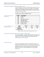
Bits 0-5 of this register are not used. Bits 6 & 7 of this register are used to
indicate the bank of registers to be addressed. In Enhanced Mode, three
banks (banks 0-2) of eight registers may be addressed. Bank 0 is similar to
the Standard Mode bank of registers. Bank 1 allows the 32 event inputs to
be monitored and controlled. Bank 2 registers control the debounce
circuitry of the event inputs. Bits 7 and 6 of this register select the bank as
follows:

