


31
!
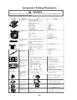
WARNING
To avoid risk of electrical shock, personal injury or death; disconnect power to oven and discharge capacitor
before servicing, unless testing requires power.
Illustration
Component
Test
Results
Transformer
Discharge Capacitor
Remove all wires from terminals.
Measure resistance from:
230 to COM..................................................
208 to COM..................................................
230 to Ground..............................................
208 to Ground..............................................
Terminal 5 to 6.............................................
Terminal 4 to Ground...................................
Less than 1
Ω
Less than 1
Ω
Infinite
Infinite
Less than 1
Ω
Approximately
Ω
Convection blower
motor
Use Service test to verify operation
ST1-1 to ST1-3
BK BU
Convection heating
element
Disconnect wires from terminals.
Measure resistance across heating
element.
Element
2000 W .......................
Approximately 19 - 22
Ω
Radiant heating
element
Disconnect wires from terminals.
Measure resistance across heating
element.
Element
3000 W ......................... Approximately 14
Ω
Resistance thermal
device (RTD)
Temperature
32
°
F
.............................................................
350
°
...........................................................
Resistance
1000
Ω
1654
Ω
0
1
2 4 6 8
Relay (Power)
This relay contains a
diode in the coil
circuit.
Measure resistance from:
Terminal 0 to terminal 1 (coil) ............
0
1
2
4 6
8
Approximately 6 to 7 M
NOTE:
Analog meter is recommended
for measurement.
NOTE:
If using a digital meter it must
contain a battery of 6 volts minimum.
Wire harness
High voltage board
to display module
harness
Test continuity of wires .......................
Indicates continuity
Ω
----------------------------------------------
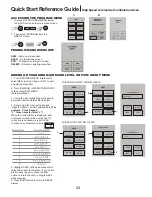
Line Voltage
ST2
GN - YL - OR -BU-------------------------------
Disconnect ST2
Fan should operate at
High Speed
Primary switch
Secondary switch
Monitor Interlock
switch
Com
NO
NC
ST1
ST2
NC to Com
NO to Com
Indicates continuity
Indicates infinity
COM
NC
NO
NC to Com
NO to Com
Indicates continuity
Indicates infinity
3
1
2
1 to 2
1 to 3
Indicates continuity
Indicates infinity
(0
°
C)
(177
°
C)
46
7
6
2
8
3
1
5
4
9
10
Limiter
Note:
Unit must have
power applied to test
Limiter.
Red - Orange Lead Terminals
Line Voltage
Yellow - Yellow Leads disconnected from
Limiter
24vdc across yellow leads
(Polarity must be correct)
Terminal 6 - Terminal 7
0
Ω
Indicates continuity
..
.......................
.
.......................
....................... .......................
Transformer, control
(AXP20QT Only)
(1) RD to (5) OR ------------------------------------
(6) BR to (10) VT ------------------------------------
Approximately 40
Ω
or Line Voltage
Approximately 1
Ω
or 28 vac
Nut
15/16”
(26mm)
Deep Socket
Component Testing Procedures


