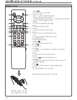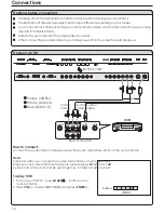
background image

23.Panel protection

---The PDP panel used in this product is made of glass.

Therefore, it can break when the product is dropped or impacted upon by
other objects. Be careful not to be injured by broken glass pieces in case
the PDP panel breaks.

24.Pixel defect

---The PDP panel is a very high technology product, giving you finely detailed pictures.

Occasionally, a few non-active pixels may appear on the screen as a fixed point of blue, green or red.
Please note that this does not affect the performance of your product.

Important Safety Precautions

(continued)

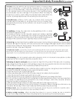
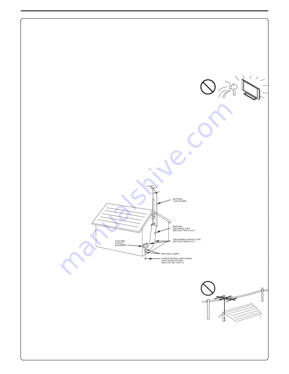
EXAMPLE OF ANTENNA GROUNDING AS PER

NATIONAL ELECTRICAL CODE

NEC—NATIONAL ELECTRICAL CODE

<

If an outside antenna is connected to the television equipment, be sure the antenna system is
grounded so as to provide some protection against voltage surges and built-up static charges.
Section 810 of the National Electrical Code provides information with respect to proper grounding of
the mast and supporting structure, grounding of the lead-in wire to an antenna discharge unit, size of
grounding conductors, location of antenna-discharge unit, connection to grounding electrodes, and
requirements for the grounding electrode.

<

An outside antenna system should not be located in the vicinity of
overhead power lines or other electric light or power circuits, or where it
can collide with such power lines or circuits. When installing an outside
antenna system, extreme care should be taken to keep from touching
such power lines or circuits, as contact with them might be fatal.

22. Power source

---This product is intended to be supplied by a listed power supply indicated on the

marking label. If you are not sure of the type of power supply to your home, consult your product dealer
or local power company. For added protection for this product during a lightning storm, or when it is left
unattended and unused for long periods of time, unplug it from the wall outlet and disconnect the
cable system. This will prevent damage to the product due to lightning and power line surges. When the
unit has to be used with another power supply voltage, the power cable must be changed. Consult your
product dealer. The socket outlet should be installed near the equipment and easily accessible. Use
only the power cord designated by our dealer to ensure safety and EMC. When connecting other
products such as VCRs and personal computers, you should turn off the power of the unit for protection
against electric shock.

4

Summary of Contents for AR4200

Page 1: ...2 inch Plasma TV Model No AR4200 For assistance please call 1 800 619 3848 Before connecting operating or adjusting this product please read these instructions completely Please keep this manual for f...

Page 2: ...hannels in Memory Automatically 19 Setting Auto Fine Tune AFT 20 Manual Fine Tuning 20 Adding and Erasing Channels 20 Changing Channels 21 Adjusting the Volume 21 Select input source signal 22 Selecti...

Page 3: ...VGA Mode 34 Adjusting Picture 34 Adjusting the Phase and Frequency 34 Adjusting the Picture Automatically 34 Changing the Scaling mode of Image 35 Changing the Position of Image 35 Displaying the Info...

Page 4: ...all amount of mercury Disposal of these materials may be regulated due to environmental considerations For disposal or recycling information please contact your local authorities or the Electronic Ind...

Page 5: ...ng 7 Do not block any ventilation openings Install in accordance with the manufacturer instructions The vents and other openings in the cabinet are designed for ventilation Do not cover or block these...

Page 6: ...uids Never insert an object into the product through vents or openings High voltage flows in the product and inserting an object can cause electric shock and or short internal parts For the same reaso...

Page 7: ...es and requirements for the grounding electrode An outside antenna system should not be located in the vicinity of overhead power lines or other electric light or power circuits or where it can collid...

Page 8: ...erate the PDP TV functions replace the batteries in the remote control Slide the cover while pressing down Place the batteries with their terminals corresponding to the and indications in the battery...

Page 9: ...L PIC AUDIO PIC AUDIO SPEAKER DVI AV OUTPUT AV OUTPUT AV INPUT AV INPUT CONTROL COMPONENT INPUT 1 COMPONENT INPUT 1 COMPONENT INPUT 2 COMPONENT INPUT 2 D SUB D SUB AUDIO AUDIO C P r r C P r r C P r r...

Page 10: ...The antenna requirements for good color television reception are more important than those for black white television reception For this reason a good quality outdoor antenna is strongly recommended...

Page 11: ...OL button to directly increase or decrease the sound volume level In OSD Menu press these buttons to adjust the value or setting of each item Press these two buttons to directly change the TV channel...

Page 12: ...Shares audio input with AV input Connect to the VGA audio output jacks on your PC Y Pb Cb Pr Cr Audio Video Audio L R Video Audio L R Component inputs 2 Y Pb Cb Pr Cr Audio 6 Headphone jack 7 AV outp...

Page 13: ...6 CH VOL Use to adjust volume To access picture mode select menu 8 0 9 digit buttons Direct channel select 9 SOURCE To access source select menu 10 MUTE Sound mute 11 ENTER To confirm your operation...

Page 14: ...icture frame from headphone 24 MENU To access the MENU main page 25 To move upward or downward in menu operation To adjust zoom rate in ZOOM mode and pan picture in PAN mode To select picture frame in...

Page 15: ...to SOURCE VOL AV ENTER To play VCR Audio cable source VIDEO A D C1C2 TV Cautions before connecting Carefully check the terminals for position and type before making any connections The illustration o...

Page 16: ...nd set it to output mode For details refer to your camcorder user SOURCE VOL AV VIDEO and press to confirm ENTER To playback Camcorder R L VIDEO AUDIO Note The operations of the camcorder may be diffe...

Page 17: ...te audio L red audio R P C Green Y Blue P C r b R G B R G B Connections continued D SUB SVHS HEADPHONE RF PIC AUDIO PIC AUDIO DVI AV OUTPUT AV INPUT CONTROL COMPONENT INPUT 1 COMPONENT INPUT 2 D SUB A...

Page 18: ...nect the Video cable between the Y Pb Pr input jacks on the unit and Y Pb Pr output jacks on the DTV receiver Connections continued D SUB SVHS HEADPHONE RF PIC AUDIO PIC AUDIO DVI AV OUTPUT AV INPUT C...

Page 19: ...GA jack on the PC and the VGA input jack on the unit Connect an Audio cable between the AUDIO output on the PC and AUDIO input jack on the unit VGA cable Connections continued D SUB SVHS HEADPHONE RF...

Page 20: ...s between the Audio L R jacks on the unit and external amplifier or To Audio inputs 1 Turn on your PDP TV select AV or TV source 2 Turn the main volume of the amplifier to minimum 3 Turn on the amplif...

Page 21: ...em Use to confirm or access items of menu On screen menu will disappear from the screen automatically after about 15 seconds or you can press CH VOL ENTER 5 6 1 2 To clearly introduce the menu operati...

Page 22: ...to select item CH source 6 5 Press to select or VOL antenna cable 6 If you are connected to an antenna please select antenna the selected item displays in green If you connect cable please select cabl...

Page 23: ...to select or VOL on off When the item is set to on the selected channel will be erased off the selected channel will be added The erased channels can not be selected by using the buttons unless you us...

Page 24: ...e volume VOL VOL increase decrease Using the MUTE button At any time you can temporarily turn off the sound using the button MUTE Press the button and the sound turns off MUTE 1 To turn mute off press...

Page 25: ...V Select TV signal YCbCr1 YCbCr1 YCbCr2 YCbCr2 settings menu background language close caption mode close caption off on on mute close capt background source select opaque cc1 English right left to so...

Page 26: ...g Channel Label channel up down to change channels up down left right to edit label source to clear label menu to return Use to select a channel you want add label to CH5 6 8 Press to select item CH e...

Page 27: ...ect menu P M picture mode 1 2 Press to select a desired picture mode VOL 3 Press to exit MENU There are three preset picture modes and and one user set picture mode Each preset mode has its own pictur...

Page 28: ...display the menu main MENU 1 Setting Sleep Timer Press the button to display menu SLP sleep time 1 Press to adjust VOL 2 3 Press to exit MENU Sleep time menu to return right left to adjust off setting...

Page 29: ...the display aspect ratio is less than 4 3 this mode crops the picture by 16 5 percent on all sides and fills the panel with the remaining picture Changing Screen Options Changing the Scaling mode of I...

Page 30: ...row keys to pan select for zoom menu to exit Press to adjust zoom ratio CH5 6 5 The unit allows you to pan the picture after you zoom in the picture You can quickly access Zoom menu by using the butto...

Page 31: ...ce headphone MTS auto volume off on STEREO 50 50 Press to display menu page VOL audio 2 Using the S M button Adjusting the Headphone Volume Press to display the menu main MENU 1 Press repeatedly to se...

Page 32: ...lume every time the channel is changed Auto volume lets you automatically adjust the volume of the desired channel by lowering the sound output when the modulation signal is high or by raising the sou...

Page 33: ...em CH5 6 3 Press or to confirm VOL ENTER 4 Press to display menu page VOL layout 2 Using the Layout Menu Press the button to display the select MODE screen layout 1 Press to confirm ENTER 3 Press to s...

Page 34: ...play on the screen Main Frame Split Frame Main Frame 2 3 4 Scanning Frame Grid When this item is selected the screen displays 9 scanning frames 3 6 9 1 4 7 2 5 8 Scanning Frame 31 When this item is se...

Page 35: ...ng SPEAKER The selected frame displays with a green border Viewing the Picture in Picture Press to display the menu main page MENU 1 Press twice to select item CH pip 6 3 Press or to display pip frame...

Page 36: ...ge VOL window 2 Press to adjust the size of PIP frame VOL 4 Press to exit MENU 5 Press the button to quickly access the select menu POS pip position 1 Press to select a desired position for the pip fr...

Page 37: ...are automatically activated AUTO Auto running picture brightness contrast phase frequency 50 50 50 50 right left to adjust brightness picture brightness contrast phase frequency 50 50 50 right left t...

Page 38: ...PC adjust the position of the screen if it is not well aligned Press to display window menu page VOL 2 Displaying the Information When the button is pressed in PC VGA mode the unit displays some info...

Page 39: ...Menu 5 Press to display window menu page VOL 2 50 h wide 36 Changing the Scaling mode of Image Press to display the m e n u m a i n page MENU 1 Press to select item CH image size 6 3 Press to select o...

Page 40: ...when mute If you select the and can not be accessed unless you mute the sound on mute close caption mode close capt background Setting the Background of Closed Caption Press to display the menu main p...

Page 41: ...7 X NR GENERAL AUDIENCES All ages admitted PARENTAL GUIDANCE SUGGESTED Some material may not be suitable for children RESTRICTED Under 17 requires accompanying parent or adult guardian NO ONE 17 AND U...

Page 42: ...an be set but this Rating is not normally broadcast by TV Station Content Rating can be set D L S V FV Sexually Suggestive Dialog Adult Language Sexual Situation Violence Fantasy Violence Example 1 Ex...

Page 43: ...e V CHIP menu if you input the right password or you will be denied The default password is you may change the password yourself 000000 Changing the Password From the menu page press to select item pa...

Page 44: ...utomatically block the higher ratings R NC 17 X also When TV Y7 in the age based rating is set to BLOCK this will automatically block the higher ratings TV G TV PG TV 14 and TV MA In addition if you b...

Page 45: ...poor picture quality occurs when having activated an S VHS camera or camcorder connected and having connected another peripheral at the same time In this case switch off one of the other peripherals C...

Page 46: ...s On Screen Audio Equalizer Standby consumption Unit W stand AC100V 240V 60 50Hz RS232 1 Service only Wall mounting bracket included User friendly OSD Menu Headphone mini stereo jack 1 3 5mm Composite...

Page 47: ...continued Display Format Supported by This Unit For VGA 640X480 60Hz 72 75 85 Hz Hz Hz 800X600 60Hz 72Hz 75Hz 85Hz 1024X768 60Hz 75Hz 85Hz For YPbPr 480P 50Hz 59Hz 60Hz 720P 50Hz 59Hz 60Hz 1080i 50Hz...

Page 48: ...Dimensional Drawings 1050 645 733 110 287 79 1247 777 Design and specifications are subject to change without notice 45 Unit mm...

Reviews: