


24 / Chapter 3 Installation
9.
Primary / Secondary IDE connectors (Two 40-pin Blocks)
These connectors support the provided IDE hard diskribbon cable.
After connecting the single end to the board, connect the two
plugs at the other end to your hard disk no space(s) . If you install
two hard disks, you must configure the second drive to Slave
mode by setting its jumper settings. BIOS now supports SCSI
device or IDE CD-ROM boot up (see "HDD Sequence SCSI/IDE
First" & "Boot Sequence" in the BIOS Features Setup of the BIOS
SOFTWARE) (Pin 20 is removed to prevent inserting in the wrong
orientation when using ribbon cables with pin 20 plugged) .
Tip
:
You may configure two hard disks to be both Masters us-
ing one ribbon cable on the primary IDE connector. You
may install one operating system on an IDE drive and
another on a SCSI drive and select the right one through
BIOS Feature Setup.
10.
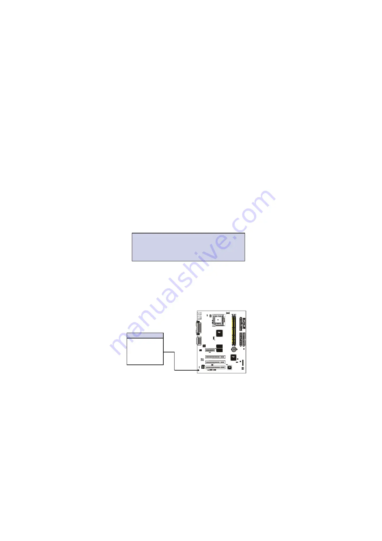
IrDA / Fast IR-Compliant infrared module connector - JP11/JP12
This connector supports the optional wireless transmitting and
receiving infrared module. This module mounts to a small open-
ing on system cases that support this feature. You must also
configure the setting through UART2 Use Infrared” in Chipset
Feature Setup to select whether UART2 is directed for use with
COM2 or IrDA. Use the five pins as shown on the Back View
and connect a ribbon cable from the module to the motherboard
according to the pin definitions.
IR Connector
Pin
Description
1
+5V
2
NC
3
IRRX
4
Ground
5
IRTX
USB
COM 1
VGA
AM R SL OT
PCI SLOT 3
PCI SLOT 2
PCI SLOT 1
MIDI
GAM E
AU DIO
JP 20 JP 18
CD 1 CD 2
2MB SDRAM
2MB SDRAM
T : K / B
B: Mou se
Printer
JP 19
PANE L
JP 2
JP 11
JP 12
S B-LINK
JP 16
JP 17
JP 8 JP 9
RT1
FAN 1
Jp5
JP 1
JP 6
JP 14
JP 15
JP 4
FAN 2
4 Mb it
F irm w a re
H U B (F W H )
I/O
Co nt roller
HU B ( IC H)
AUDIO
CODEC
RT2
JP 13


