background image


PC 8175  User’s Manual


1. 

Supervisor password: 

You can enter and change the options on 

the setup menu. 

2. 

User password: 

You can just enter, but have no right to change 

the options on the setup menu. 


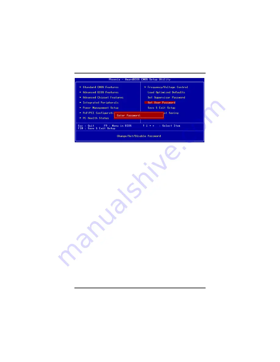
When you select this function, the following message will appear at 

the center of the screen to assist you in creating a password. 


ENTER PASSWORD


Type a maximum eight-character password, and press <Enter>. This 

typed password will clear previously entered password from the 

CMOS memory. You will be asked to confirm this password. Type this 

password again and press <Enter>. You may also press <Esc> to 

abort this selection and not enter a password. 

52 

Appendix


Summary of Contents for PC 8175

Page 1: ...PC 8175 17 TFT Touch Panel Computer User s Manual...

Page 2: ......

Page 3: ...is document ACNODES makes no commitment to update or to keep current the information contained in this manual ACNODES reserves the right to make improvements to this document and or product at any tim...

Page 4: ...er there is no guarantee that interference will not occur in a particular installation If this equipment does cause harmful interference to radio or television reception which can be determined by tur...

Page 5: ...C 8175 is properly grounded 4 The brightness of the flat panel display decreases with usage However hours of use vary depending on the application environment 5 Turn OFF the system power before cleani...

Page 6: ...c electricity on your body When handling boards and components wear a wrist grounding strap available from most electronic component stores Trademarks Acknowledgments Acnodes is a trademark of Acnodes...

Page 7: ...3 This page does not contain any information...

Page 8: ...ion 3 1 3 Dimensions 3 1 4 Front View and I O Outlets 5 1 4 1 Front View 5 1 4 2 I O Outlet 6 1 5 Package list 7 C h a p t e r 2 8 Hardware Installation 8 2 1 CPU and DRAM Installation 9 2 2 HDD Insta...

Page 9: ...7 Advanced Chipset Features 39 A 8 Integrated Peripherals 41 A 9 Power Management Setup 45 A 10 PnP PCI Configuration Setup 48 A 11 PC Health Status 49 A 12 Frequency Voltage Control 50 A 13 Load Opti...

Page 10: ...hich equipped with Intel Core 2 Duo processors and 17 SXGA LCD display The paradigmatic industrial panel computer PC8175 is a complete full function and extreme cost effective industrial HMI controlle...

Page 11: ...ck 533 667MHz f Watchdog Timer Up to 255 levels as Reset feature 1 2 2 I O System f Standard I O a 3 x serial ports with power 2 x RS 232 1 x RS 232 422 485 a 1 x PS 2 for Keyboard Interface a 1 x PS...

Page 12: ...Dimension main body size 414 5 x 325 3 x 78 9mm f Operating temperature O to 45 C Relative umidity 50 f Relative humidity 10 to 85 40 C non condensing f Altitude 10 000 ft 3 000 meters f Vibration ope...

Page 13: ......

Page 14: ...PC 8175 User s Manual 1 4 Front View and I O Outlets 1 4 1 Front View The figure below shows the features and controls on the PC8175 front bezel SEL SEL Backlight ON OFF Introduction 5...

Page 15: ...4 2 I O Outlet The following figure shows the I O locations of the PC8175 1 PS2 x 2 KB MS 6 USB v2 0 x 4 2 COM 1 7 Mic in Line Out 3 VGA 8 COM 2 COM 3 4 Giga LAN x 2 9 Power Switch 5 IEEE 1394a x 2 10...

Page 16: ...f you can not find it please contact ACNODES distributors 1 P1175 831 x 1 2 AC power cord x 1 3 Panel mount kit x 7 4 CD driver x1 5 Wall VESA mount bracket kit x 1 Optional 6 Rack mount bracket kit x...

Page 17: ......

Page 18: ...e Installation The PC 8175 provides lots of flexible ways for user to select different configuration such as CPU Hard Disk and more The chapter will show you how to install the hardware It includes m...

Page 19: ...andard PC 8175 system is designed for Core 2 Duo level CPUs The CPU board provides two 240 pin DDR2 DIMM socket that supports system memory up to 3GB When upgrading the CPU DRAM please refer to the fo...

Page 20: ...PC 8175 User s Manual 10 Hardware Installation 2 Install the CPU and DDR DRAM in the PC 8175...

Page 21: ...s to install If you want to install one or two 2 5 HDD the PC 8175 also provides the 3 5 to 2 5 drive holder to meet your requirement Please follow the steps Note There is the hardware limitation so t...

Page 22: ...PC 8175 User s Manual 12 Hardware Installation 3 Installation complete...

Page 23: ...PC 8175 User s Manual In addition installing the 2 5 HDD please follow the steps 1 Changing HDD rubber from 3 5 HDD bracket to 2 5 HDD bracket 2 Installation complete Hardware Installation 13...

Page 24: ...XD Receive data 7 RTS Request to send 3 TXD Transmit data 8 CTS Clear to send 4 DTR Data terminal ready 9 RI 5V 12V Ring indicator 5 GND ground 2 4 VGA The PC 8175 has an analog RGB interface connecto...

Page 25: ...Rack VESA Desktop mount There are four application options for the PC8175 Panel Wall Rack VESA mountings 2 6 1 Panel Mount The PC8175 is designed for panel mount application To mount the PC8175 the s...

Page 26: ...ual 16 Hardware Installation 2 6 2 Wall Mount The PC8175 is designed for Wall mount application The wall mount kit is optional Please refer to the following figure 1 Screw 6 screws to fix wall mount b...

Page 27: ...175 User s Manual Hardware Installation 17 2 6 3 Rack Mount The PC8175 also support rack mount The rack mount kit is optional Please refer to the following procedure 1 Screw 5 screws each side 2 Compl...

Page 28: ...tallation 2 6 4 VESA Mount The PC8175 provides two ways for VESA mount 75x75 mm and 100x100 mm The VESA mount bracket is the same as wall mount bracket Please refer to the following steps 1 Assemble w...

Page 29: ......

Page 30: ...1 System PC 8175 could support with Windows Vista XP To facilitate installation system driver you should read the instructions in this chapter carefully before you attempt installation 1 Panel series...

Page 31: ...s RS 232 Baud Rate 19200 baud rate fixed Resolution 1024 x 1024 10 bit A D converter inside Power Input 5V to 12V DC Power Consumption 12V 27mA i where i v touch screen sheet R 5V 23mA i where i v tou...

Page 32: ...llation of the touch screen driver you should read the instructions in this chapter carefully before you attempt installation 1 Insert Driver CD and select the Panel series P1175 831 Driver Step5 Touc...

Page 33: ...PC 8175 User s Manual Driver Installation 23 4 Select the Standard Calibrate tab...

Page 34: ...Mount software driver 1 Insert Driver CD and select the Panel series P1175 831 Driver Step5 Touch Driver DOS Setup exe 2 Press ENTER key to install the drivers to drive C or use keyboard to key in the...

Page 35: ...rogram is able to skip the IRQ number detecting if you Touchscreen Driver Installation 13 do not need to detect the specified IRQ number For example you do not need to detect IRQ5 and the command is C...

Page 36: ...unt Touch Screen The display will show the initialization message PenMount V7 06 Copyright c SALT International Corp Test COM n IRQ n n is the number after PMDETECT done PenMount communication setting...

Page 37: ...PC 8175 User s Manual Driver Installation 27 This page does not contain any information...

Page 38: ......

Page 39: ......

Page 40: ...l Alt and Esc keys simultaneously when the following message appears at the bottom of the screen during POST Power on Self Test TO ENTER SETUP PRESS DEL KEY If the message disappears before you respon...

Page 41: ...olors F2 to select color Shift F2 key forward Shift F2 to select color backward Reserved F3 key Reserved F4 key Restore the previous CMOS value from CMOS only F5 key for Option Page Setup Menu Load th...

Page 42: ...end to configure then press Enter to accept or enter its sub menu NOTE If your computer can not boot after making and saving system changes with Setup the Award BIOS will reset your system to the CMOS...

Page 43: ...t the value you want in each item a Date The date format is day date month year Press F3 to show the calendar day It is determined by the BIOS and read only from Sunday to Saturday date It can be keye...

Page 44: ...rmation should be provided in the documentation from your hard disk vendor or the system manufacturer If the HDD interface controller supports ESDI select Type 1 If the HDD interface controller suppor...

Page 45: ...stop and you will be prompted The system booting will not stop for a keyboard error it will stop for other errors All But Keyboard The system booting will not stop for a disk error it will stop for ot...

Page 46: ...l A 6 Advanced BIOS Features This section allows you to configure and improve your system to set up some system features according to your preference a CPU Feature Scroll to this item and press Enter...

Page 47: ...e CPU Internal Cache item on the menu Appendix Enabled Enable cache Disable cache Disabled a Hyper Threading Technology Use this item to enable or disable Hyper Threading Technology which makes a sing...

Page 48: ...devices option above The default setting is Enabled a Boot Up Floppy Seek During POST BIOS will determine the floppy disk drive type 40 or 80 tracks 360Kb type is 40 tracks while 720Kb 1 2MB and 1 44M...

Page 49: ...ars Sec This option refers to character numbers typed per second by the keyboard The default value is 6 6 6 characters per second 8 8 characters per second 10 10 characters per second 12 characters pe...

Page 50: ...t type anything just press Enter and it will disable the security Once the security is disabled the system will boot and you can enter Setup freely a APIC Mode Use this item to enable or disable APIC...

Page 51: ...al specifications of your system hardware a DRAM Timing Selectable Use this item to increase the timing of the memory This is related to the cooling of memory a CAS Latency Time You can select CAS lat...

Page 52: ...error may result The default value is Disabled a Video BIOS Cacheable This item allows you to change the Video BIOS location from ROM to RAM Video Shadow will increase the video speed a PCI Express Ro...

Page 53: ...egrated Peripherals This section allows you to configure your SuperIO Device IDE Function and Onboard Device a OnChip IDE Device Scroll to this item and press Enter to view the sub menu OnChip IDE Dev...

Page 54: ...lautomatically remove the IDE rimaryMaster Slave PIO and or IDE Secondary Master Slave PIO items on the menu IDE Master Slave PIO The four IDE PIO Programmed Input Output fields let you set a PIO mode...

Page 55: ...using the EHCI USB2 0 controller in the system USB Keyboard Support Enable this item if the system has a Universal Serial Bus USB controller and you have a USB keyboard AC 97 Audio Select Use this ite...

Page 56: ...Paralellel Port This item allows you to determine access onboard parallel port controller with which I O address The options available are 378H IRQ7 278H IRQ5 3BC IRQ7 Disabled Parallel Port Mode Sel...

Page 57: ...Advanced Configuration and Power Management ACPI The function is always Enabled a ACPI Suspend Type This item specifies the power saving modes for ACPI function If your operating system supports ACPI...

Page 58: ...rites blanks to the video buffer SYNC Blank Select this option if your monitor supports the Display Power Management Signaling DPMS standard of the Video Electronics Standards Association VESA Use the...

Page 59: ...power switch this option will delay the complete system power OFF sequence by approximately 4 seconds Within this delay period system will temporarily enter into Suspend Mode enabling you to restart...

Page 60: ...available are PCI Slot AGP a Reset Configuration Data Normally you leave this item Disabled Select Enabled to reset Extended System Configuration Data ESCD when you exit Setup or if installing a new a...

Page 61: ...A bus architecture The default value is PCI ISA PnP a PCI VGA Palette Snoop Some non standard VGA display cards may not show colors properly This item allows you to set whether MPEG ISA VESA VGA Cards...

Page 62: ...verVoltage and AGP voltage a Auto Detect PCI Clk The enabled item can automatically disable the clock source for a PCI slot without a module to reduce EMI ElectroMagnetic Interference a Spread Spectru...

Page 63: ...nual To load CMOS SRAM with SETUP default values please enter Y If not please enter N A 14 Set Supervisor User Password You can set a supervisor or user password or both of them The differences betwee...

Page 64: ...n the following message will appear at the center of the screen to assist you in creating a password ENTER PASSWORD Type a maximum eight character password and press Enter This typed password will cle...

Page 65: ...n enter Setup freely PASSWORD DISABLED When a password is enabled you have to type it every time you enter the Setup It prevents any unauthorized persons from changing your system configuration A 15 S...

Page 66: ...16 Exit Without Saving Select this option to exit the Setup utility without saving changes you have made in this session Type Y and it will quit the Setup utility without saving your modifications Ty...

Page 67: ...re range and dynamic load regulation OUTPUT RATING Nominal Regulation Min Max Output Ripple Noise 1 3 3V 5 50mV 0 3A 16 8A 2 5V 5 50mV 0 3A 12 0 A 3 12V 5 120mV 1 5A 10 0 A 4 12V 10 120mV 0 0 A 0 8A 5...

Page 68: ...A 0 0A HLLL 3 3V MAX 16 8 A 0 3 A 1 5A 0 0A other MIN LLHL 12V MAX other MIN 0 3 A 0 3 A 10 0A 0 0A ALL MIN LLLL 0 3 A 0 3 A 1 5A 0 0A HOLD UP TIME FULL LOAD 115V 60Hz 17 mSec Minimum 230V 50Hz 17 mSe...

Page 69: ...t has been removed and the power switch has been turned off for no more than 2 seconds OVERLOAD PROTECTION Overload currents defined as a 10 amp sec fault current ramp starting from full load applied...

Page 70: ...AC Full Load 68 minimum 230 VAC Full Load B 1 3 ENVIRONMENTAL REQUIREMENTS f Operating temperature range 0 C to 50 C f Storage temperature range 20 C to 80 C f Humidity non condensing 5 95 RH Non Cond...

Reviews: