

Chapter 2 Hardware Configuration
2-3. HOW TO SET THE JUMPERS
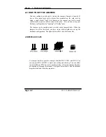
You can configure your board by setting the jumpers. Jumper is consists of
two or three metal pins with a plastic base mounted on the card, and by
using a small plastic
"
cap
"
, Also known as the jumper cap (with a metal
contact inside), you are able to connect the pins. So you can set-up your
hardware configuration by
"
opening
"
or
"
closing
"
pins.
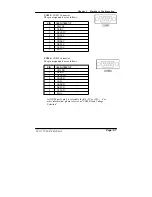
The jumper can be combined into sets that called jumper blocks. When the
jumpers are all in the block, you have to put them together to set up the
hardware configuration. The figure below shows how this looks like.
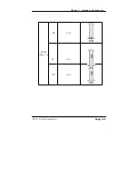
JUMPERS AND CAPS
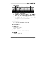
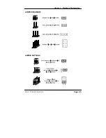
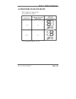
If a jumper has three pins for example, labelled PIN1, PIN2, and PIN3. You
can connect PIN1 & PIN2 to create one setting and shorting. You can either
connect PIN2 & PIN3 to create another setting. The same jumper diagrams
are applied all through this manual. The figure below shows what the manual
diagrams look and what they represent.
Page: 2-4
PC 5171 USER
’
S MANUAL
Summary of Contents for PC 5171
Page 1: ...USER S MANUAL PC 5171 Socket 478 P4 P4 M 17 inch Panel PC System...
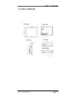
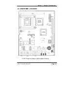
Page 9: ...Chapter 1 Introduction 1 2 CASE ILLUSTRATION PC 5171 USERc MANUAL Page 1 3...
Page 96: ...Appendix A System Assembly Diagram 2 PC 5171 USERcS MANUAL Page A 7...
Page 98: ...Appendix A System Assembly Diagram 2 PC 5171 USERcS MANUAL Page A 9...
Page 104: ...Appendix A System Assembly Diagram 2 Remove CD ROM PC 5171 USERcS MANUAL Page A 15...
Page 105: ...Appendix A System Assembly EXPLODED DIAGRAM FOR REMOVING MASK Page A 16 PC 5171 USERcS MANUAL...
Page 107: ...Appendix A System Assembly Diagram 2 Page A 18 PC 5171 USERcS MANUAL...
Page 108: ...Appendix A System Assembly Diagram 3 Diagram 4 PC 5171 USERcS MANUAL Page A 19...
Page 110: ...Appendix B Technical Summary BLOCK DIAGRAM Page B 2 PC 5171 USERcS MANUAL...


