Acnodes KD 8191 User Manual Download Page 16

P.13


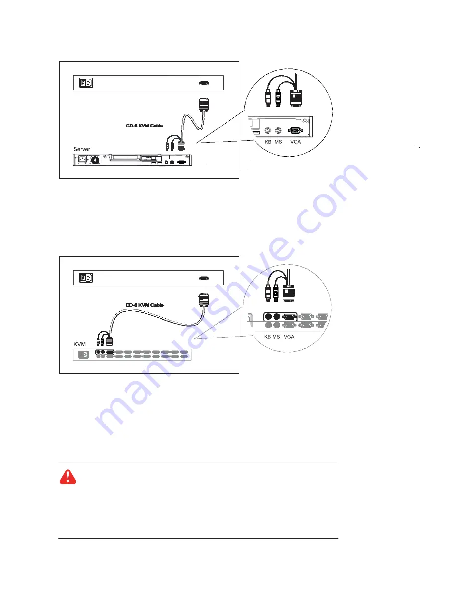
1.15  Connect to Server via PS/2 Interface 

Chapter 1


Figure 12. 

Example of connecting CD-6 3-in-1 PS/2 KVM cable to server via PS/2 interface


1.16  Connect to KVM via PS/2 Interface


Figure 13. 

Example of connecting CD-6 3-in-1 PS/2 KVM cable to KVM via PS/2 interface


Remarks :


The above connection is only for the LCD keyboard without KVM switch built-in.


For the LCD keyboard drawer with KVM switch built-in, please refer to attached KVM switch user manual.


Caution : 

The LCD keyboard drawer is hot-pluggable, but components of connected de- 

vices, such as the servers and KVM switch, may not be hot-pluggable. Plugging and un- 
plugging cables while servers and KVM are powered on may cause irreversible damage to


the servers, KVM and LCD keyboard drawer. Before attempting to connect anything to the 
LCD keyboard drawer, we suggest turning off the power to all devices before connecting 
them. Apply power to connected devices again only after the LCD keyboard is receiving


power. The company is not responsible for damage caused in this way.


Summary of Contents for KD 8191

Page 1: ...User Manual KD 8191 1U 19 inch LCD monitor Keyboard Drawer...

Page 2: ......

Page 3: ...rface 12 1 13 Connect to KVM via USB Interface 12 1 14 Connect to Server via PS 2 Interface 13 1 15 Connect to KVM via PS 2 Interface 13 Chapter 2 Operation 2 1 On screen Display Operation 14 2 2 On s...

Page 4: ...re water lightning or other acts of nature unauthorized product modifi cation or failure to follow instructions supplied with the product Repair or attempted repair by anyone not authorized by us Any...

Page 5: ...t from the power outlet to prevent being damaged by transient over voltage Keep all liquids away from the equipment to minimize the risk of accidental spillage Liquid spilled on to the power supply or...

Page 6: ...rear mounting L bracket x 1 pair N117 119 series mounting depth adjustable from 315 to 880mm N1417 1419 series mounting depth adjustable from 140 to 710mm 4 2 in 1 USB KVM cable x 1 pc and CD 6 3 in 1...

Page 7: ...the standard parts shown on the package contents Check and make sure they are included and in good condition If anything is missing or damage contact the supplier immediately 1 6 Optional Accessories...

Page 8: ...to release the 2 pt lock 2 2 point lock 3 LCD interchangeable module kit 4 LCD membrane 5 Adjustable rear mounting L bracket 6 Micro switch for screen auto power off 7 Membrane switch KVM option 8 Ke...

Page 9: ...easure the front and rear mounting depth of the rack Align each rear L bracket to a suitable length and tighten the fasteners shown in Figure 2 Figure 2 Aligning the rear L brackets to a suitable leng...

Page 10: ...front of the LCD shown in Figure 4 Figure 4 Pulling the tab toward the front of LCD Flip up the LCD to a suitable angle shown in Figure 5 Figure 5 Flipping up the LCD to a suitable angle Figure 6 Oper...

Page 11: ...on Figure 8 Pushing the white arrow button Push the white arrow button on either side of the LCD keyboard drawer to unlock shown in Figure 8 Avoid pressing the red button located on either side Hold d...

Page 12: ...6 5 6 3 7 7 Front mounting ear left right x 2 pcs Support bracket x 4 pcs M6 cage nut x 8 pcs M6 washer x 8 pcs M6 15mm screw x 8 pcs M3 2 4 5mm screw x 14 pcs Install the Front Mounting Ear x 2 pcs 1...

Page 13: ...ttach support brackets to chassis with M3 2 4 5mm screw x 3 pcs Repeat the above step for the other side Pickup the chassis 3 Insert inner members of slides into the already mounted internal slide mem...

Page 14: ...nstallation Slides Chapter 1 Install into rack 4 Hold down the white arrow button and push the chassis to the end Attach left and right mounting ears to vertical mounting rails Tighten the screws on b...

Page 15: ...ia USB interface 1 14 Connect to KVM via USB Interface Figure 11 Example of connecting CB 6 2 in 1 USB KVM cable to KVM via USB interface Remarks The above connection is only for the LCD keyboard with...

Page 16: ...e refer to attached KVM switch user manual Caution The LCD keyboard drawer is hot pluggable but components of connected de vices such as the servers and KVM switch may not be hot pluggable Plugging an...

Page 17: ...ight Green On Orange Power saving Power on off LCD Display the OSD menu Scrolls through menu options and adjusts the displayed control Exit the OSD screen Shortcut key to auto adjustment by pressing t...

Page 18: ...d size An Adjusting message is displayed during the process PHASE CLOCK Phase Clock To enter into the phase clock sub menu H V POSITION H V Position Align the screen image left or right and up or down...

Page 19: ...Hz 640 x 480 60 72 75Hz 800 x 600 60 70 72 75Hz 1024 x 768 60 70 72 75Hz 1152 x 864 60 70 75Hz Resolution 1280 x 1024 60 70 75Hz Plug Play DDC EDID 1 3 Console Port Combo 3 in 1 DB 15 connector for VG...

Page 20: ...P 17 3 2 Keyboard Mouse Chapter 3 Supporting layouts keyboard integrated with touchpad T keyboard integrated with trackball...

Page 21: ...Option with cost efficient DB 15 KVM integration with either 8 or 16 ports Please ask your supplier for full KVM details 4 2 DVI D Option External power version 3 in 1 VGA KB mouse console port Remark...

Page 22: ...P 19 4 4 S Video BNC Input Option Chapter 4 External power version S Video BNC 3 in 1 VGA KB mouse console port Remarks Package includes an extra 6ft S Video cable...

Page 23: ...en image left or right V Position Align the screen image up or down Clock Adjust the clock value Phase Adjust the phase value 3 Function OSD Position Adjust OSD menu horizontal and vertical position O...

Page 24: ...Sharpness Saturation X X Image Hue X X Auto Config N A N A N A H Position N A N A N A V Position N A N A N A Clock N A N A N A Geometry Phase N A N A N A OSD Position OSD Zoom Function Color Temp Lang...

Page 25: ...Volt 48 Volt Input range 9 18V 18 36V 36 75V Input current No load 50 mA 50 mA 50 mA Full load 4950 mA 2450 mA 1220 mA Output rating Output voltage 12 Volt 12 Volt 12 Volt Output current 4 16A 4 16A...

Page 26: ...ng the phase or pixel rate automatically or manually 3 The membrane button power light is not ON Press the power On Off on LCD membrane button to check if the monitor is in the ON mode Check the power...

Page 27: ...05 x 175 mm 22 9 x 27 8 x 6 9 16 kg 35 lb 20 kg 44 lb The company reserves the right to modify product specifications without prior notice and assumes no responsibility for any error which may appear...

Reviews: