background image

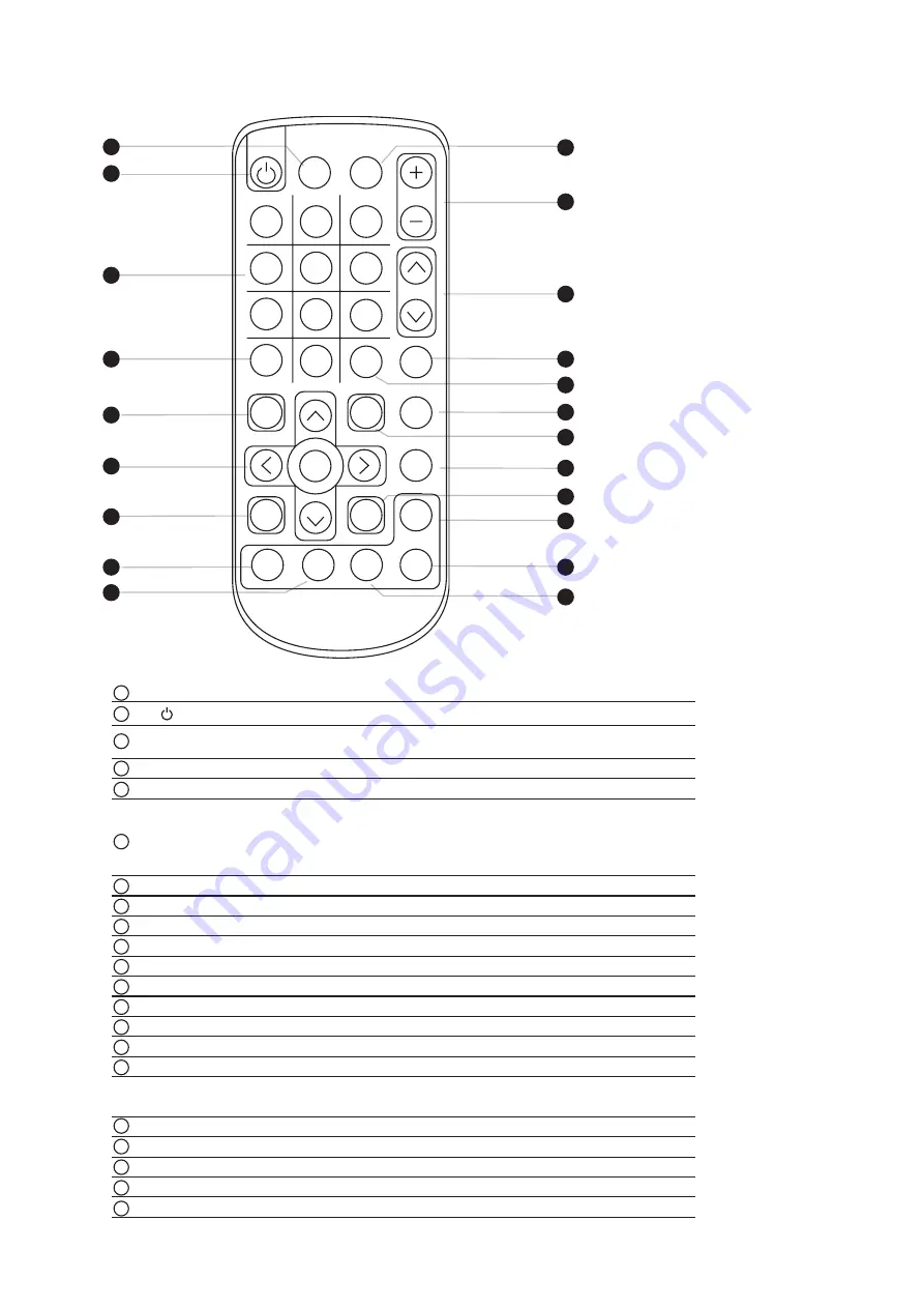
How to Use RC-2 Remote Controller

1

2

3

4

5

6

AUTO

0

-/--

7

8

9

PIP

MENU

SELECT

BACK

EXIT

SOURCE

POSITION

SWAP

PIP

AUDIO

ASPECT

SLEEP

PIP

ENTER

CH

FREEZE

MUTE

INPUT

VOL

Water proof

1

4

3

2

5

7

6

20

21

8

9

10

8

11

12

1

12

13

15

16

17

18

1

19

14

14

INPUT

Select the source

Switches on or o

  the TV

0 - 9

Only use in TV mode. Select channels. For channel numbers 10 and 

above, enter the second digit within two seconds.

AUTO

Auto adjust

MENU

Display the menu on the screen or go to the previous menu

▲ / ▼ / ◄ / ► / 

ENTER

Go to the upper menu or select the previous value /

Go to the next menu or select the next value / 

Decrease the setting value / 

Increase the setting value or enter to the select item setting

Enter to the select item settings or excude the setting

BACK

Back to previous value

MUTE

Turn on or o

  the speaker

Vol + / -

Increase or decrease the speaker volume

CH + / -

For TV model only, increase or decrease the channel number

FREEZE

Reserve for OEM model

- / --

For setting input single or double digits

ASPECT

Adjust the screen size

SELECT

To select the existing item

SLEEP

Select the sleeping time

EXIT

Exit the menu or cancel

PIP functions

PIP

Picture in picture

PIP AUDIO

To set the audio of in PIP mode

POSITION

To set the screen position in PIP mode

SOURCE

PIP Source

SWAP

Swap screen in PIP mode

1

8

2

3

4
5

6

7

9

10

11

12
13
14
15
16

17
18
19
20
21

P.11

Summary of Contents for APH 8190

Page 1: ...H8190 All rights reserved Product description and product specifications are subject to change without notice For latest product information please visit Acnodes website at www acnodes com 14628 Central Ave Chino CA 91710 Tel 909 597 7588 Fax 909 597 1939 Copyright 2020 Acnodes Corp Industrial Monitors User Manual ...

Page 2: ...d open the chassis Opening it yourself could damage the equipment and invalidate its warranty If any part of the equipment becomes damaged or stops functioning have it checked by qualif ed service personnel What the warranty does not cover Any product on which the serial number has been defaced modified or removed Damage deterioration or malfunction resulting from Accident misuse neglect f re wate...

Page 3: ...ations On screen Display Operation OSD P 7 Part 3 Options 3 1 3 2 3 3 3 4 3G HD SD SDI Broadcast grade input MCS Multi display control solution AV4 4 Upgrade HDMI Audio Remote Controller DP Upgrade DP Audio Remote Controller Projected Capacitive 10 point touch Resistive 1 point touch DC Power 12V 24V 48V 125V Sunlight Readable Auto Dimming 3 5 P 12 3 6 P 14 P 15 P 8 P 9 P 10 ...

Page 4: ... monitors and monitor screens can scratch the LCD display or strip off the finish Do not spray any kind of liquid directly onto the screen or case of your monitor Spraying liquids directly onto the screen or case can cause damage which is not covered under warranty Do not use paper towels or abrasive pads to clean your monitor Using an abrasive pad or any wood based paper product such as paper towe...

Page 5: ...0 1 1 Package Content 19 LCD display X 1 6ft VGA cable X 1 Power adapter X 1 Power cord X 1 Mounting hardware X 1 pack Mounting bracket x 4 pcs M4 6mm screw x 8 pcs M4 50mm screw x 8 pcs APH8190 HDMI DP upgrade I O DP Audio Built in Dual Stereo Speakers 2W x 2 3 5mm audio jacks for audio in out P 1 ...

Page 6: ... 384 1 mm 18 8 x 2 5 x 15 1 inch 651 x 124 x 597 mm 25 6 x 4 9 x 23 5 inch 7 7 kg 16 9 lb 10 5 kg 23 1 lb Rear case LCD panel Protective 3mm glass 6mm aluminum front bezel Audio speaker for HDMI or Audio option LCD membrane Remote sensor 1 2 3 4 5 6 7 Front View 7 Bottom View Rear View Side View 1 2 Structure Diagram P 2 ...

Page 7: ...Front View Side View Rear View 1 2 Dimension UNIT mm 1mm 0 03937 inch Bottom View P 3 ...

Page 8: ...unting brackets with 8 x M4 6mm screws Adjust the LCD panel with 8 x M4 50mm screws and f x it on the surface Steps Hardware set part no UV BK 2 Hardware and M4 4 pcs for VESA mount are not provided VESA mount 100 100mm M4 screw 1 3 Installation I Panel mount II VESA mount 100 100mm P 4 ...

Page 9: ... 294 Display area mm 376 32H x 301 06V Surface treatment Haze 25 Hard coating Surface hardness 3H Backlight type LED MTBF hrs 30 000 Power Input Auto sensing 100 to 240VAC 50 60Hz Consumption Screen ON Max 39W Power saving mode Max 2W Power button OFF Max 1W Compliance EMC FCC CE certif ed Safety CE LVD certif ed Environment RoHS3 REACH compliant Video VGA Analog 0 7Vp p DVI DVI D single link Opti...

Page 10: ...I 1 2 1280 x 720 x 50 60Hz 720p 720 x 480 x 50 60Hz 576p 480p Audio Signal 2ch Linear PCM In some circumstances if the user connects the LCD to PC via HDMI port for video and audio signals the LCD may display incorrectly on a full screen If so please adjust the display card setting on display size to fix the issue Physical Specification APH8190 APH8190 IP Product W x D x H mm 476 5 x 63 6 x 384 1 ...

Page 11: ...wer light Green On Orange Power saving Membrane Switch Function OSD Configuration Page Image for the brightness contrast color temp red green and blue Geometry for the auto adjust H position V position phase and clock Video for the colour tint sharpness noise reduction DCDi and TV Setup Audio for volume bass treble balance AVL and mute Misc for the language OSD position graphic mode ratio reset an...

Page 12: ...x 1 0 8Vp p 75 ohm 3G SDI OUT BNC x 1 Active through equalized relocked Standard Compliance Video SMPTE 425M 274M 296M 125M ITU R BT 656 Audio SMPTE 299M 272M C Compatible Audio Format 3G SDI 48kHz 16 20 24 bit 2 CH Synchronized Video HD SDI 48kHz 16 20 24 bit 2 CH Synchronized Video SD SDI 48kHz 16 20 24 bit 2 CH Synchronized Asyn chronized Video Compatible Video Format 3G SDI 1080p 1080p 1080i 7...

Page 13: ...protocol of MCS control at https www acnodes com files downloads MCS UM pdf More control is always good Especially when it is necessary and easy Acnodes provides MCS solution to control the OSD of various LCD display up to 64 units The RS 232C is used for the communication between the PC and the first display via a 15 feet serial cable while the CAN bus is used for the various LCD displays cascade...

Page 14: ...on display size to fix the issue 2 HDMI and DP upgrade option comes with RC 2 remote controller x 1 please refer to P 11 Audio Power out in in Video PC VGA DVI D Audio Built in Dual Stereo Speakers 2W x 2 3 5mm audio jacks for audio in out Audio Built in Dual Stereo Speakers 2W x 2 3 5mm audio jacks for audio in out DP Upgrade Options DP 3 3 Options Upgrade I O HDMI Upgrade Options HDMI HDMI P 10 ...

Page 15: ...or select the next value Decrease the setting value Increase the setting value or enter to the select item setting Enter to the select item settings or excude the setting BACK Back to previous value MUTE Turn on or off the speaker Vol Increase or decrease the speaker volume CH For TV model only increase or decrease the channel number FREEZE Reserve for OEM model For setting input single or double d...

Page 16: ...itive 5 Wire Resistive Touch Point 10 Single Input Type Finger or Capacitive Stylus Finger or Stylus Resolution 2048 x 2048 2048 x 2048 Touch Point Accuracy 10 mm offset Response Speed Max 20 ms 15 ms Activation Force 10 g 50 g Surface Hardness 7H 3H Light Transmission 88 80 3 Haze 2 8 3 Durability 100 million touches 10 million touches Top Layer 1 8 mm Tempered Glass ITO Film Bottom Layer Film ITO...

Page 17: ...er 3 4 Options Touchscreen Driver TPC 10 Driver TRB TCB Driver Please follow the below steps to setup the touch screen Step 1 Run the bundled CD disc Step 2 Double click the Setup exe Step 3 Follow the installation instruction to finish the setup Step 4 After installation run the TouchKit program the 4 point calibration Please do the initial calibration after the first setup P 13 ...

Page 18: ...75V 66 160V Input current No load 50 mA 50 mA 50 mA 35 mA Full load 4950 mA 2450 mA 1220 mA 749 mA Output rating Output voltage 12 Volt 12 Volt 12 Volt 12 Volt Output current 4 16A 4 16A 4 16A 6 25A Efficiency 84 85 85 91 3 5 Options DC Power 1 If the unit with LCD earthing may be required For DC power option P 14 ...

Page 19: ...uto dimming is ON users cannot adjust brightness from OSD menu Steps OSD Menu Picture Auto Dimming ON DS 01 is a IP54 dimming knob installed on the bottom right side of the front panel The display can support hyper dimming function to adjust brightness from nearly 0 to 100 via the easy to use knob One click on dimming knob causes 2 increase or decrease on display brightness Options Switch Dimming ...

Reviews: