background image


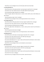
Frost2 
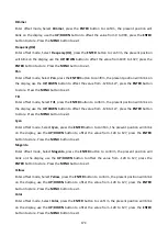
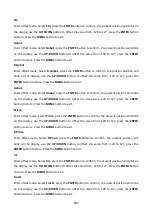
Enter offset mode, Select Frost2, press the ENTER button to confirm, the present position will blink 
on the display, use the UP/DOWN  button to offset the value from -128  to 127, press the  ENTER 
button to store. Press the MENU button to exit. 
Focus 
Enter offset mode, Select Focus, press the ENTER button to confirm, the present position will blink 
on the display, use the UP/DOWN  button to offset the value from -128 to 127, press the  ENTER 
button to store. Press the MENU button to exit. 
Zoom 
Enter offset mode, Select Zoom, press the ENTER button to confirm, the present position will blink 
on the display, use the UP/DOWN  button  to offset the value from -128 to 127, press the  ENTER 
button to store. Press the MENU button to exit. 
BladeDW1 
Enter offset mode, Select BladeDW1, press the ENTER button to confirm, the present position will 
blink on the display, use the UP/DOWN button to offset the value from 0 to 255, press the ENTER 
button to store. Press the MENU button to exit. 
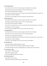
BladeDW2 
Enter offset mode, Select BladeDW2, press the ENTER button to confirm, the present position will 
blink on the display, use the UP/DOWN button to offset the value from 0 to 255, press the ENTER 
button to store. Press the MENU button to exit. 
BladeUP1 
Enter offset mode, Select BladeUP1, press the ENTER button to confirm, the present position will 
blink on the display, use the UP/DOWN button to offset the value from 0 to 255, press the ENTER 
button to store. Press the MENU button to exit. 
BladeUP2 
Enter offset mode, Select BladeUP2, press the ENTER button to confirm, the present position will 
blink on the display, use the UP/DOWN button to offset the value from 0 to 255, press the ENTER 
button to store. Press the MENU button to exit. 
BladeLF1 
Enter offset mode, Select BladeLF1, press the ENTER button to confirm, the present position will 
blink on the display, use the UP/DOWN button to offset the value from 0 to 255, press the ENTER 
button to store. Press the MENU button to exit. 


19C 

Summary of Contents for Aeco 10-HR

Page 1: ......

Page 2: ... 6 4 Color Gobo 7 5 How To Set The Unit 7 5 1 Main Function 7 5 2 Home Position Adjustment 15 6 Control By Universal DMX Controller 20 6 1 DMX512 Connection 20 6 2 Address Setting 21 6 3 DMX512 Configuration 22 7 Error Information 31 8 Troubleshooting 36 9 Fixture Cleaning 37 1C ...

Page 3: ...ion slots is blocked otherwise the unit will be overheated Before operation ensure that you are connecting this product to the proper voltage in accordance with the specifications in this manual or on the product s specification label It s important to ground the yellow green conductor to earth in order to avoid electric shock Minimum ambient temperature TA 0 Maximum ambient temperature TA 40 Do n...

Page 4: ...ied out by unskilled people can lead to damage or malfunction Please contact the nearest authorized technical assistance center if needed Disconnect this product from its power source before servicing DO use the original packaging if the device is to be transported Avoid direct eye exposure to the light source while the product is on DO NOT operate this product if you see damage on the housing shi...

Page 5: ...m 0 100 various strobe speeds Color Wheel 1 color wheel with 5 colors plus white Gobo Wheel 1 static gobo wheel with 8 gobos plus open 1 rotating gobo wheel with 7 gobos plus open convenient replacement Control DMX Channel 34 25 29 channels Protocols DMX512 RDM Art Net sACN Firmware upgrade via DMX link or USB Disk Construction Display LCD display backlit touch button Data In Out 3 pin XLR 5 pin X...

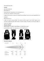
Page 6: ...t They can be used independently and overlayed Motorized linear iris 4 fast and smooth framing shutters The position and the angle of each shutter blade can be controlled individually Each shutter blade can block out light completely The framing module can rotate at 45 degrees Dimension Weight 364x252x658mm 24 5kgs 364x252x692mm 26 8kgs with clamp 14 3 x10 x26 in 54lbs 14 3 x10 x27 2 in 59 1lbs wi...

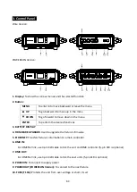
Page 7: ...TTERY DISPLAY 4 FIRMWARE UPGRADE Used to upgrade the fixture s firmware 5 ETHERNET Transfers fixture s information to a main controller 6 DMX IN For DMX512 link use 3 pin XLR cable to link the unit and DMX controller 5 pin XLR is optional 7 DMX OUT For DMX512 link use 3 pin XLR cable to link the next units 5 pin XLR is optional 8 POWER IN To connect to supply power 9 POWER OUT POWERCON Version To ...

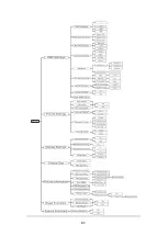
Page 8: ...ened 5 How To Set The Unit 5 1 Main Function Turn on the unit press the MENU button into menu mode and press the UP DOWN button until the required function is shown on the monitor Select the function by the ENTER button Use the UP DOWN button to choose the submenu press the ENTER button to store and automatically return to the last menu Press the MENU button or let the unit idle 30 seconds to exit...

Page 9: ...8C ...

Page 10: ... stops Hold fixture continues to obey the last command it received Via DMX if DMX signal stops or Manual the fixture will automatically read the DMX value in the Manual Test menu for operation after selecting this mode press the ENTER button to store Press the MENU button back to the last menu or let the unit idle 30 seconds to exit menu mode Connect Option To select Connect Option press the ENTER...

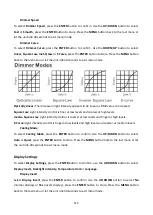
Page 11: ...NTER button to confirm use the UP DOWN button to select Pan Invert Tilt Invert P T Feedback Dimmer Speed Dimmer Curve or Cooling Mode Pan Invert To select Pan Invert press the ENTER button to confirm Use the UP DOWN button to select No normal or Yes pan invert press the ENTER button to store Press the MENU button back to the last menu or let the unit idle 30 seconds to exit menu mode Tilt Invert T...

Page 12: ...vels Inverse Square Law Light intensity control is coarser at low levels and finger at high levels S Curve Light intensity control is finger at low levels and high levels and coarser at medium levels Cooling Mode To select Cooling Mode press the ENTER button to confirm Use the UP DOWN button to select Auto or Quiet press the ENTER button to store Press the MENU button back to the last menu or let ...

Page 13: ...est To select Fixture Test press the ENTER button to confirm use the UP DOWN button to select Auto Test or Manual Test Auto Test Select Auto Test press the ENTER button to confirm the unit will run built in programs to automatically test pan tilt color gobo gobo rotation animation prism prism rotation frost focus zoom etc Press the MENU button back to the last menu or exit menu mode after auto tes...

Page 14: ...t Temperature press the ENTER button to confirm fixture temperature will show on the display press the MENU button to exit Fan State Select Fan State press the ENTER button to confirm fan state will show on the display press the MENU button to exit USB Upgrade File Select USB Upgrade File press the ENTER button to confirm USB upgrade file will show on the display press the MENU button back to exit...

Page 15: ...tton to confirm use the UP DOWN button to select No normal or Yes the unit will run built in program to reset effect to their home positions press the ENTER button to store Press the MENU button to exit All Reset Select All Reset press the ENTER button to confirm use the UP DOWN button to select No normal or Yes the unit will run built in program to reset all motors to their home positions press E...

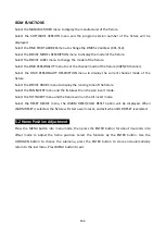
Page 16: ...e of the fixture Select the DEVICE HOURS menu to display the running time of the fixture Select the PAN INVERT menu and the fixture will run the pan invert mode Select the TILT INVERT menu and the fixture will run the tilt invert mode Select the RESET DEVICE menu the WARM RESET COLD RESET option will be displayed When WARM RESET is selected the fixture will start a warm reset and exit when COLD RE...

Page 17: ...16C ...

Page 18: ...ton to offset the value from 128 to 127 press the ENTER button to store Press the MENU button to exit Cyan Enter offset mode Select Cyan press the ENTER button to confirm the present position will blink on the display use the UP DOWN button to offset the value from 128 to 127 press the ENTER button to store Press the MENU button to exit Magenta Enter offset mode Select Magenta press the ENTER butt...

Page 19: ...o offset the value from 128 to 127 press the ENTER button to store Press the MENU button to exit Prism Enter offset mode Select Prism press the ENTER button to confirm the present position will blink on the display use the UP DOWN button to offset the value from 128 to 127 press the ENTER button to store Press the MENU button to exit R Prism Enter offset mode Select R Prism press the ENTER button ...

Page 20: ...offset the value from 0 to 255 press the ENTER button to store Press the MENU button to exit BladeDW2 Enter offset mode Select BladeDW2 press the ENTER button to confirm the present position will blink on the display use the UP DOWN button to offset the value from 0 to 255 press the ENTER button to store Press the MENU button to exit BladeUP1 Enter offset mode Select BladeUP1 press the ENTER butto...

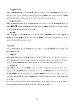
Page 21: ...to 255 press the ENTER button to store Press the MENU button to exit BladeRG2 Enter offset mode Select BladeRG2 press the ENTER button to confirm the present position will blink on the display use the UP DOWN button to offset the value from 0 to 255 press the ENTER button to store Press the MENU button to exit Framing Enter offset mode Select Framing press the ENTER button to confirm the present p...

Page 22: ... to reduce signal errors 6 3 pin XLR connectors are more popular than 5 pins XLR 3 pin XLR Pin 1 GND Pin 2 Negative signal Pin 3 Positive signal 5 pin XLR Pin 1 GND Pin 2 Negative signal Pin 3 Positive signal Pin4 Pin5 not used 6 2 Address Setting If you use a universal DMX controller to control the units you have to set DMX address from 1 to 512 so that the units can receive DMX signal Press the ...

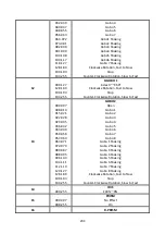
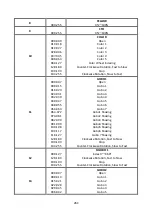
Page 23: ...L VALUE FUNCTION 1 000 255 PAN 0 540 2 000 255 PAN FINE 3 000 255 TILT 0 270 4 000 255 TILT FINE 5 000 255 PAN TILT SPEED Fast to Slow 6 000 255 CYAN 0 100 7 000 255 MAGENTA 0 100 8 000 255 YELLOW 0 100 9 000 255 CTO 0 100 10 000 009 010 018 019 027 028 036 037 045 046 063 064 127 128 189 190 193 194 255 COLOR Open Color 1 Color 2 Color 3 Color 4 Color 5 Color Wheel Indexing Counter Clockwise Rota...

Page 24: ...ckwise Rotation Fast to Slow Stop Counter Clockwise Rotation Slow to Fast 13 000 007 008 014 015 021 022 028 029 035 036 042 043 049 050 056 057 063 064 071 072 079 080 087 088 095 096 103 104 111 112 119 120 127 128 189 190 193 194 255 GOBO 2 Open Gobo 1 Gobo 2 Gobo 3 Gobo 4 Gobo 5 Gobo 6 Gobo 7 Gobo 8 Gobo 1 Shaking Gobo 2 Shaking Gobo 3 Shaking Gobo 4 Shaking Gobo 5 Shaking Gobo 6 Shaking Gobo ...

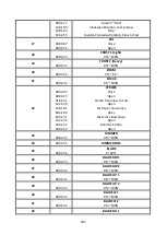
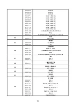
Page 25: ...100 22 000 007 008 015 016 131 132 139 140 181 182 189 190 231 232 239 240 247 248 255 STROBE Close Open Strobe from Slow to Fast Open Fast Open Slow Close Open Fast Close Slow Open Open Random Strobe Open 23 000 255 DIMMER 0 100 24 000 255 DIMMER FINE 25 000 255 BLADE 0 180 26 000 255 BLADE DW 1 0 100 27 000 255 BLADE DW 2 0 100 28 000 255 BLADE UP 1 0 100 29 000 255 BLADE UP 2 0 100 30 000 255 B...

Page 26: ...er Curve Linear Dimmer Curve S Standard Quiet Null LED Frequency Setting Enable LED Frequency Setting Disable Null Focus Compensate Disable Focus Compensate Near Focus Compensate Medium Focus Compensate Far Null Dimmer Speed Fast Dimmer Speed Smooth Reset All Reset Effect Reset Pan Tilt Null 25 Channels Mode 2 CHANNEL VALUE FUNCTION 1 000 255 PAN 0 540 2 000 255 PAN FINE 3 000 255 TILT 0 270 4 000...

Page 27: ...072 073 081 082 090 091 099 100 108 109 117 118 127 128 189 190 193 194 255 GOBO 1 Open Gobo 1 Gobo 2 Gobo 3 Gobo 4 Gobo 5 Gobo 6 Gobo 7 Gobo1 Shaking Gobo2 Shaking Gobo3 Shaking Gobo4 Shaking Gobo5 Shaking Gobo6 Shaking Gobo 7 Shaking Clockwise Rotation Fast to Slow Stop Counter Clockwise Rotation Slow to Fast 12 000 127 128 189 190 193 194 255 R GOBO 1 Index 0 360 Clockwise Rotation Fast to Slow...

Page 28: ...st 14 000 255 IRIS 100 0 15 000 007 008 255 PRISM No Effect On 16 000 127 128 189 190 193 194 255 R PRISM Index 0 360 Clockwise Rotation Fast to Slow Stop Counter Clockwise Rotation Slow to Fast 17 000 007 008 255 CRI Close Open 18 000 255 FROST 1 Light 0 100 19 000 255 FROST 2 Heavy 0 100 20 000 255 ZOOM 54 6 5 21 000 255 FOCUS 0 100 22 000 007 008 015 016 131 132 139 140 181 182 189 190 231 232 ...

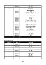
Page 29: ...e Inv Square Law Dimmer Curve Linear Dimmer Curve S Standard Quiet Null LED Frequency Setting Enable LED Frequency Setting Disable Null Focus Compensate Disable Focus Compensate Near Focus Compensate Medium Focus Compensate Far Null Dimmer Speed Fast Dimmer Speed Smooth Reset All Reset Effect Reset Pan Tilt Null 29 Channels Mode 2 CHANNEL VALUE FUNCTION 1 000 255 PAN 0 540 2 000 255 PAN FINE 3 000...

Page 30: ...Slow Stop Clockwise Rotation Slow to Fast 11 000 255 IRIS 100 0 12 000 007 008 255 CRI Close Open 13 000 255 FROST 1 Light 0 100 14 000 255 FROST 2 Heavy 0 100 15 000 255 ZOOM 54 6 5 16 000 255 FOCUS 0 100 17 000 007 008 015 016 131 132 139 140 181 182 189 190 231 232 239 240 247 248 255 STROBE Close Open Strobe from Slow to Fast Open Fast Open Slow Close Open Fast Close Slow Open Open Random Stro...

Page 31: ...80 089 090 099 100 109 110 119 120 129 130 139 140 149 150 159 160 169 170 179 180 189 190 199 200 209 210 219 220 229 230 255 SPECIAL FUNCTION Null Dimmer Curve Square Law Dimmer Curve Inv Square Law Dimmer Curve Linear Dimmer Curve S Standard Quiet Null LED Frequency Setting Enable LED Frequency Setting Disable Null Focus Compensate Disable Focus Compensate Near Focus Compensate Medium Focus Com...

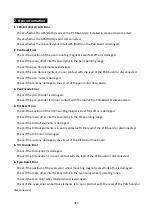
Page 32: ...h the lead of the PCB board or disconnected 4 Tilt Reset Error Check if the position of the tilt mounting magnetic steel falls off or is damaged Check if there are other interference items in the tilt operating range Check if the tilt Hall elements is damaged Check if the tilt Hall elements is in poor contact with the lead of the PCB board or disconnected Check if the tilt motor is damaged Check i...

Page 33: ...el Hall elements is damaged Check if the yellow color wheel Hall elements is in poor contact with the lead of the PCB board or disconnected Check if the yellow color wheel motor is damaged Check if there is any damage to the circuit of the yellow color wheel motor drive board 9 Cto Reset Error Check if the position of the cto mounting magnetic steel falls off or is damaged Check if there are other...

Page 34: ... poor contact with the lead of the PCB board or disconnected Check if the gobo wheel1 motor is damaged Check if there is any damage to the circuit of the gobo wheel1 motor drive board 13 Blade Reset Error Check if the position of the blade mounting magnetic steel falls off or is damaged Check if there are other interference items in the blade operating range Check if the blade Hall elements is dam...

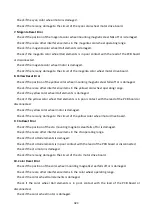
Page 35: ...d Check if there is any damage to the circuit of the focus motor drive board 17 Zoom Reset Error Check if the position of the zoom mounting magnetic steel falls off or is damaged Check if there are other interference items in the zoom operating range Check if the zoom Hall elements is damaged Check if the zoom Hall elements is in poor contact with the lead of the PCB board or disconnected Check if...

Page 36: ...s are installed in place or disconnected Check if the fan is damaged Check if there are other interference items in the fan operating range 25 HeadFan1 2 3 4 5 6 7 Stop Err Check if the fan circuit on the motherboard breaks down Check if the component is damaged 26 HeadFan1 2 3 4 5 6 7 Too Low Check if the fan is out of order Check if there are other interference items in the fan operating range 2...

Page 37: ...fan is out of order Check if the fan circuit on the motherboard breaks down The position of each fan of the fixture 8 Troubleshooting Following are a few common problems that may occur during operation Here are some suggestions for easy troubleshooting A The unit does not work no light and the fan does not work 1 Check the connect power and main fuse 2 Measure the mains voltage on the main connect...

Page 38: ...t working well 1 The stepper motor might be damaged or the cable connected to the PCB is broken 2 The motor s drive IC on the PCB might be out of condition 9 Fixture Cleaning The cleaning of internal and external optical lenses and or mirrors must be carried out periodically to optimize light output Cleaning frequency depends on the environment in which the fixture operates damp smoky or particula...

Page 39: ...38C ...

Page 40: ...Innovation Quality Performance ...

Reviews: