background image

MODEL

(Btu/h)

Static Pressure

(Pa/in.wg)

0~100/0~0.4

18K

0~160/0~0.64

24K

0~160/0~0.64

30K~36K

0~160/0~0.64

42K~60K

0~50/0~0.2

9K

0~50/0~0.2

12K

Indoor Unit

Installation 

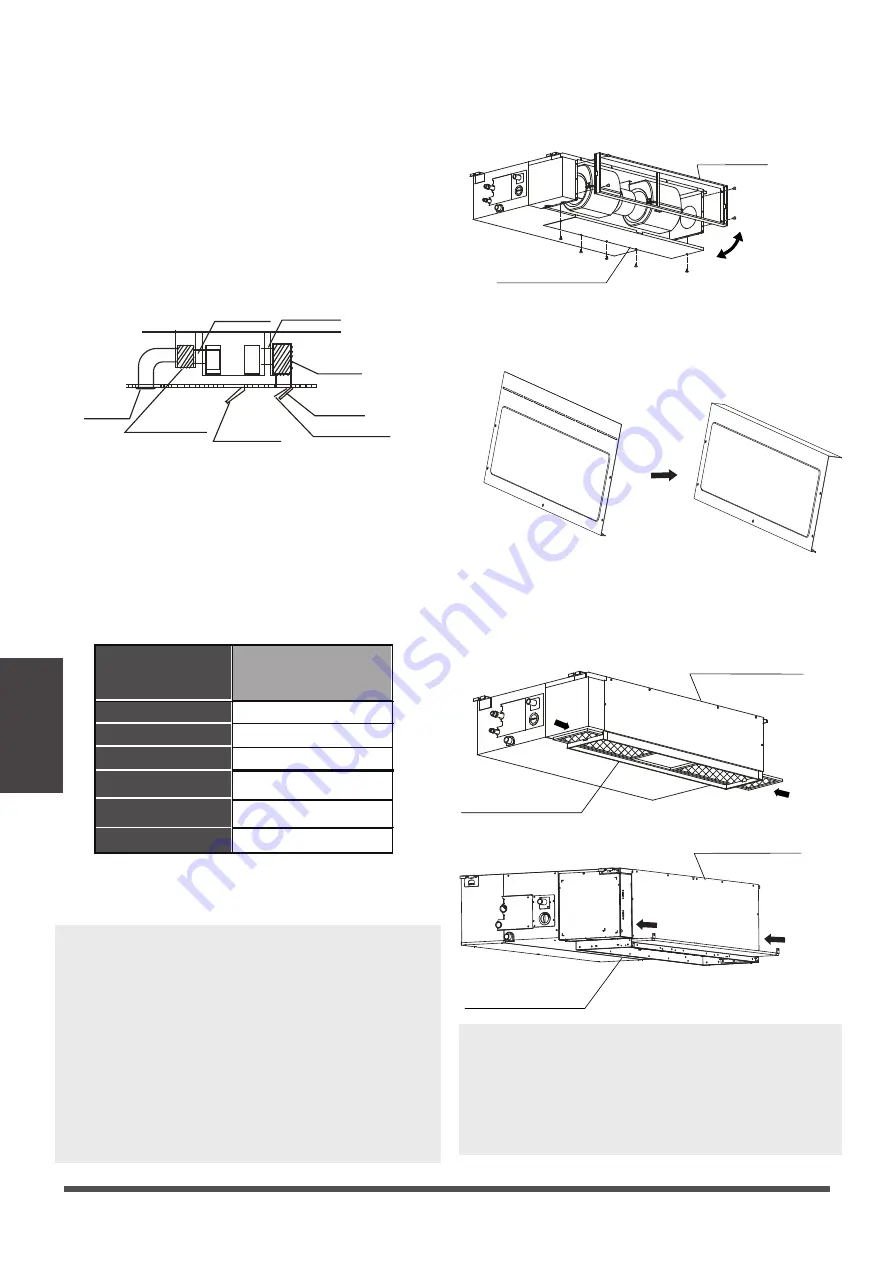
Step 4: Adjust the air inlet direction
(From rear side to under-side)

Step 3: Duct and accessories installation

NOTE: 

1. Do not place the connecting duct weight on 

     the indoor unit.

NOTE: 

The min. length of the duct should be
more than 1m, and fix on the air inlet
by screws(applicable to the unit that the
air inlet filter is not fasten by screws).


2.When connecting the duct, use an 

   nonflammable canvas tie-in to prevent 

   vibrating.

3.Insulation foam must be wrapped outside 

   the duct to avoid condensate. An internal 

   duct underlayer can be added to reduce 

   noise, if the end-user requires.

1. Install the filter (optional) according to the size

of the air inlet.

5. Refer to the following static pressure guidelines

when installing the indoor unit.

Change the fan motor static pressure

according to external duct static pressure.

2. Install the canvas tie-in between the body and 

duct.

3. The air inlet and air outlet duct should be far

enough apart enough to a avoid air passage

short-circuit.

4. Connect the duct according to the following

diagram:

Canvas tie-in Canvas tie-in

Air outlet

Isolation booth

Isolation booth

checking orifice

Air inlet

Air dust filter

1. Take off the ventilation panel and flange.

2. Change the mounting positions of the

    ventilation panel and air return flange.

Air return flange

Ventilation panel

3. When installing the filter mesh, fit it into the

    flange as illustrated in the following figure.

NOTE:

 All the figures in this manual are for

demonstration purposes only. The air 

conditioner you have purchased may be 

slightly different in design, though similar in 

shape.

Air return flange

Ventilation panel

Air return flange

Ventilation panel

Or

Bend the rear ventilation panel 90 degrees 

along the dotted line into a descending 

ventilation panel.(some models)

 Page 22

Summary of Contents for ACiQ-09CD-HH-MB

Page 1: ...CD HH MB ACiQ 12CD HH MB ACiQ 18CD HH MB ACiQ 24CD HH MB ACiQ Concealed Duct Air Handler IMPORTANT NOTE Read this manual carefully before installing or operating your new air conditioning unit Make sure to save this manual for future reference ...

Page 2: ...Unit Specifications and Features 07 Owner s Manual Table of Contents Safety Precautions 04 Care and Maintenance 10 Troubleshooting 12 1 Indoor unit 07 2 Operating temperature 08 3 Other features 09 ...

Page 3: ...3 Power Specifications 35 3 Anchor outdoor unit 26 Refrigerant Piping Connection 28 A Note on Pipe Length 28 B Connection Instructions Refrigerant Piping 29 1 Cut pipe 29 2 Remove burrs 29 3 Flare pipe ends 29 4 Connect pipes 30 Air Evacuation 37 1 Evacuation Instructions 37 2 Note on Adding Refrigerant 38 Test Run 39 Packing and unpacking the unit 40 Installation Summary 16 3 Duct and accessories...

Page 4: ... supervised around the unit at all times operate your air conditioner in a wet room such as a bathroom or laundry room Too much exposure to water can cause electrical components to short circuit In certain functional environments such as kitchens server rooms etc the use of specially designed air conditioning units is highly recommended WARNING This symbol indicates the possibility of personnel in...

Page 5: ...sidual current device RCD having a rated residual operating current not exceeding 30mA and disconnection must be incorporated in the fixed wiring in accordance with the wiring rules For all electrical work follow all local and national wiring standards regulations and the Installation Manual Connect cables tightly and clamp them securely to prevent external forces from damaging the terminal Improp...

Page 6: ...its support please read the information for details in indoor unit installation and outdoor unit installation sections For units that have an auxiliary electric heater do not install the unit within 1 meter 3 feet of any combustible materials Do not install the unit in a location that may be exposed to combustible gas leaks If combustible gas accumulates around the unit it may cause fire Install d...

Page 7: ...et Air filter on some models Drain hose Electric control cabinet Refrigerant connecting pipe A For the unit which the filter is removed for left or right side Drain hose Refrigerant connecting pipe Air outlet Air inlet Air filter on some models B For the unit which the filter is removed from the bottom side C For the unit which the filter is removed from the back screw Air filter 1 Put the filter ...

Page 8: ...on features may activate and cause the unit to disable COOL mode HEAT mode DRY mode Room Temperature 17 C 32 C 62 F 90 F 0 C 30 C 32 F 86 F 10 C 32 C 50 F 90 F Outdoor Temperature 0 C 50 C 32 F 122 F 15 C 24 C 5 F 75 F 0 C 50 C 32 F 122 F 0 C 52 C 32 F 126 F For special tropical models 0 C 52 C 32 F 126 F For special tropical models 15 C 50 C 5 F 122 F For models with low temp cooling systems FOR ...

Page 9: ...2 C 64 F 126 F For special tropical models COOL mode HEAT mode DRY mode Fixed speed Type Default Setting When the air conditioner restarts after a power failure it will default to the factory settings AUTO mode AUTO fan 24 C 76 F This may cause inconsistencies on the remote control and unit panel Use your remote control to update the status Auto Restart some models In case of power failure the sys...

Page 10: ...ance Long Periods of Non Use If you plan not to use your air conditioner for an extended period of time do the following Turn on FAN function until unit dries out completely Turn off the unit and disconnect the power CAUTION Before changing the filter or cleaning turn off the unit and disconnect its power supply Removal and maintenance must be performed by a certified technician When removing filt...

Page 11: ...e Maintenance Pre Season Inspection After long periods of non use or before periods of frequent use do the following Page 12 Check for damaged wires Make sure nothing is blocking all air inlets and outlets Check for leaks ...

Page 12: ...tion of the unit s plastic parts Both the indoor unit and outdoor unit make noises Low hissing sound during operation This is normal and is caused by refrigerant gas flowing through both indoor and outdoor units Low hissing sound when the system starts has just stopped running or is defrosting This noise is normal and is caused by the refrigerant gas stopping or changing direction Squeaking sound ...

Page 13: ...rvice center Provide them with a detailed description of the unit malfunction as well as your model number Troubleshooting When troubles occur please check the following points before contacting a repair company Problem Possible Causes Solution Poor Cooling Performance Temperature setting may be higher than ambient room temperature Lower the temperature setting The heat exchanger on the indoor or ...

Page 14: ...e auxiliary heating device Cold air is entering through doors and windows Make sure that all doors and windows are closed during use Low refrigerant due to leak or long term use Check for leaks re seal if necessary and top off refrigerant Indicator lamps continue flashing The unit may stop operation or continue to run safely If the indicator lamps continue to flash or error codes appear wait for a...

Page 15: ...some models Connecting wire for display 2m some models Cord protection rubber ring some models Display panel Just for testing purposes only some models KJR 120G KJR 120H 1 1 1 Optional accessories There are two types of remote controls wired and wireless Select a remote controller based on customer preferences and requirements and install in an appropriate place Refer to catalogues and technical l...

Page 16: ...lation Summary Install the outdoor unit Install the drainpipe 1 2 3 4 5 MC MC 6 Install the indoor unit Evacuate the refrigeration system Connect the wires Connect the refrigerant pipes 7 Installation Summary L L1 N L2 Page 17 ...

Page 17: ...hape shall prevail NOTE The installation must be performed in accordance with the requirement of local and national standards The installation may be slightly different in different areas Unit Parts Drain pipe Connecting pipe Air inlet Air outlet Air outlet Air inlet 1 2 3 4 5 6 6 7 1 2 3 4 5 6 7 Electric control cabinet Or Page 18 Outdoor unit B Outdoor unit A 7 6 ...

Page 18: ...ces such as cabinets Kitchens that use natural gas Areas with strong electromagnetic waves Areas that store flammable materials or gas Rooms with high humidity such as bathrooms or laundry rooms Enough room exists for installation and maintenance Enough room exists for the connecting the pipe and drainpipe The ceiling is horizontal and its structure can sustain the weight of the indoor unit The ai...

Page 19: ...n A B C 18K 210 8 3 674 26 5 880 34 6 24K 36K 249 9 8 774 30 5 1100 43 3 30K 36K 249 9 8 774 30 5 1360 53 5 36K 60K 300 11 8 874 34 4 1200 47 2 air outlet opening size D E F 136 5 4 706 27 8 600 23 6 175 6 9 926 36 5 700 27 6 175 6 9 1186 46 7 700 27 6 227 8 9 1044 41 1 800 31 5 air return opening size 190 7 5 228 8 9 228 8 9 280 11 Size of mounted lug I 920 36 2 782 30 8 1140 44 9 1001 39 4 1400 ...

Page 20: ...ermine the direction of the pipes to be drawn out Especially in cases where there is a ceiling involved align the refrigerant pipes drain pipes and indoor and outdoor lines with their connection points before mounting the unit 3 Install hanging screw bolts 4 After you select an installation location align the refrigerant pipes drain pipes as well as indoor and outdoor wires with their connection p...

Page 21: ...hen installing the indoor unit Change the fan motor static pressure according to external duct static pressure 2 Install the canvas tie in between the body and duct 3 The air inlet and air outlet duct should be far enough apart enough to a avoid air passage short circuit 4 Connect the duct according to the following diagram Canvas tie in Canvas tie in Air outlet Isolation booth Isolation booth che...

Page 22: ... and will help seal it when you finish the installation process CAUTION When drilling the wall hole make sure to avoid wires plumbing and other sensitive components Wall Indoor Outdoor 12mm 0 5 inch Step 5 Fresh air duct installation Dimension Duct joint for fresh air Ø92mm 3 62 Ø113mm 4 45 MODLE 9 12 Ø125mm 4 92 Ø160mm 6 3 MODLE 18 60 Step 6 Motor and drain pump maintenance Motor maintenance Take...

Page 23: ...th of the drain hose to the unit s outlet pipe Sheath the mouth of the hose and clip it firmly with a pipe clasp 39 59 1 1 5m 1 1 Lean over 1 50 Ceiling 39 59 7 9 20cm 21 7 55cm Lean over 1 50 1 1 5m 1 1 Drainpipe installation for units with a pump Ceiling NOTE ON DRAINPIPE INSTALLATION When using an extended drainpipe tightenthe indoor connection with an additionalprotection tube This prevents it...

Page 24: ... leaks from the joints 3 Turn off the air conditioner and put the cap back on 3 Pass the drain hose through the wall hole Make sure the water drains to a safe location where it will not cause water damage or a slipping hazard NOTE The drainpipe outlet should be at least 5cm 1 9 above the ground If it touches the ground the unit may become blocked and malfunction If you discharge the water directly...

Page 25: ...t fan is at a 90 angle to the direction of the wind If needed build a barrier in front of the unit to protect it from extremely heavy winds See Figures below Strong wind Strong wind Strong wind If the unit is frequently exposed to heavy rain or snow Build a shelter above the unit to protect it from the rain or snow Be careful not to obstruct air flow around the unit If the unit is frequently expos...

Page 26: ...B do the following 1 Insert the drain joint into the hole in the base pan of the unit The drain joint will click in place 2 Connect a drain hose extension not included to the drain joint to redirect water from the unit during heating mode Seal Drain joint A B Base pan hole of outdoor unit Seal IN COLD CLIMATES In cold climates make sure that the drain hose is as vertical as possible to ensure swif...

Page 27: ...x52 5x16 14 634 24 96 404 15 9 952x1333x415 37 5x52 5x16 34 634 24 96 404 15 9 845x702x363 33 27x27 6x14 3 540 21 26 350 13 8 938x1369x392 36 93x53 9x15 43 634 24 96 404 15 9 900x1170x350 35 4x46x13 8 590 23 2 378 14 88 800x554x333 31 5x21 8x13 1 514 20 24 340 13 39 890x673x342 35x26 5x13 46 663 26 1 354 13 94 765x555x303 30 1x21 8x11 9 452 17 8 286 11 3 805x554x330 31 7x21 8x12 9 511 20 1 317 12 ...

Page 28: ... Btu h Length of piping Maximum drop height North America Australia and the eu frequency conversion Split Type 15K 25 82 10 32 8 15K 24K 30 98 4 20 65 6 24K 36K 50 164 25 82 36K 60K 65 213 30 98 4 Other Split Type 12K 15 49 8 26 18K 24K 25 82 15 49 30K 36K 30 98 4 20 65 6 42K 60K 50 164 30 98 4 Oil traps CAUTION If oil flows back into the outdoor unit s compressor this might cause liquid compressi...

Page 29: ...are them properly This will ensure efficient operation and minimize the need for future maintenance 1 Measure the distance between the indoor and outdoor units 2 Using a pipe cutter cut the pipe a little longer than the measured distance 3 Make sure that the pipe is cut at a perfect 90 angle Oblique Rough Warped 90 DO NOT DEFORM PIPE WHILE CUTTING Be extra careful not to damage dent or deform the ...

Page 30: ...ing Flare nut Pipe 3 Tighten the flare nut as tightly as possible by hand 4 Using a spanner grip the nut on the unit tubing 5 While firmly gripping the nut use a torque wrench to tighten the flare nut according to the torque values in above table NOTE Use both a spanner and a torque wrench when connecting or disconnecting pipes to from the unit Pipe gauge Tightening torque Flare dimension A Unit m...

Page 31: ... Every wire must be firmly connected Loose wiring can cause the terminal to overheat resulting in product malfunction and possible fire 10 Do not let wires touch or rest against refrigerant tubing the compressor or any moving parts within the unit 11 If the unit has an auxiliary electric heater it mustbe installed at least 1 meter 40in away from any combustible materials Wiring Wiring NOTE ON MINI...

Page 32: ...ording to NEC and CEC requirements 12 To avoid getting an electric shock never touch the electrical components soon after the power supply has been turned off After turning off the power always wait 10 minutes or more before you touch the electrical components NOTE The cographs are for explanation purpose only Your machine may be slightly different The actual shape shall prevail Indoor unit Outdoo...

Page 33: ...T CABLE SIZE The size of the power supply cable signal cable fuse and switch needed is determined by the maximum current of the unit The maximum current is indicated on the nameplate located on the side panel of the unit Refer to this nameplate to choose the right cable fuse or switch NOTE In North America please choose the right cable size according to the Minimum Circuit Ampacity indicated on th...

Page 34: ... Connect the u lugs to the terminals Match the wire colors labels with the labels on the terminal block Frmly screw the u lug of each wire to its corresponding terminal Refer to the Serial Number and Wiring Diagram located on the cover of the electric control box Connective wiring diagram Wiring diagram Control box Please prepare spanner and flat blade screwdriver before your installation work Aus...

Page 35: ...V CIRCUIT BREAKER FUSE A 25 20 32 25 32 25 45 35 MODEL Btu h 18K 19K 24K 25K 36K 37K 48K 49K 60K POWER PHASE 1 Phase 1 Phase 1 Phase 1 Phase 1 Phase 208 240V 208 240V 208 240V 208 240V 208 240V CIRCUIT BREAKER FUSE A 25 20 32 25 50 40 70 55 70 60 MODEL Btu h 36K 37K 60K 36K 37K 60K POWER PHASE 3 Phase 3 Phase 3 Phase 3 Phase 380 420V 380 420V 208 240V 208 240V CIRCUIT BREAKER FUSE A 25 20 32 25 32...

Page 36: ...5 10 15 10 15 10 15 10 POWER outdoor PHASE 1 Phase 1 Phase 1 Phase 1 Phase 1 Phase 208 240V 208 240V 208 240V 208 240V 208 240V CIRCUIT BREAKER FUSE A 25 20 25 20 40 30 50 40 50 40 MODEL Btu h 36K 37K 60K 36K 37K 60K POWER indoor PHASE 1 Phase 1 Phase 1 Phase 1 Phase 208 240V 208 240V 208 240V 208 240V CIRCUIT BREAKER FUSE A 15 10 15 10 15 10 15 10 POWER outdoor PHASE 3 Phase 3 Phase 3 Phase 3 Pha...

Page 37: ...ast 15 minutes or until the Compound Meter reads 76cmHG 105 Pa 2 3 4 5 6 Close the Low Pressure side of the manifold gauge and turn off the vacuum pump 7 Wait for 5 minutes then check that there has been no change in system pressure 8 If there is a change in system pressure refer to Gas Leak Check section for information on how to check for leaks If there is no change in system pressure unscrew th...

Page 38: ...m ft Total pipe length standard pipe length x60g 0 64oZ m ft Total pipe length standard pipe length x65g 0 69oZ m ft R410A orifice tube in the indoor unit Total pipe length standard pipe length x30g 0 32oZ m ft Total pipe length standard pipe length x65g 0 69oZ m ft Total pipe length standard pipe length x115g 1 23oZ m ft R410A orifice tube in the outdoor unit Total pipe length standard pipe lengt...

Page 39: ...ng registered correctly d Ensure the indicators on the remote control and the display panel on the indoor unit work properly e Ensure the manual buttons on the indoor unit works properly f Check to see that the drainage system is unimpeded and draining smoothly g Ensure there is no vibration or abnormal noise during operation 5 For the Outdoor Unit a Check to see if the refrigeration system is lea...

Page 40: ... packing belt 2 Take the unit out of the package 3 Remove the foam from the unit 4 Remove the packing film from the unit Packing Indoor unit 1 Put the indoor unit into the packing film 2 Put the accessories in 3 Place the packing cushion and packing support 4 Put the indoor unit into the package 5 Close the package and seal it 6 Using the packing belt if necessary Outdoor unit 1 Put the outdoor un...

Page 41: ...be in compliance with EN61000 3 11 the product MTIT4 36CWN1 QC5 Indoor Unit MTIT4 36CWN1 QC5 Outdoor Unit MOT4V 36CN1 QC5 shall be connected only to a supply of the system impedance Zsys 0 024 Ω or less Before connecting the product to public power network please consult your local power supply authority to ensure the power network meet above requirement To be in compliance with EN61000 3 11 the p...

Page 42: ...ns are subject to change without prior notice for product improvement Consult with the sales agency or manufacturer for details Any updates to the manual will be uploaded to the service website please check for the latest version ...

Reviews: