


Automation Components, Inc.
2305 Pleasant View Road | Middleton, WI 53562
Phone:
1-888-967-5224 |
Website:
workaci.com
Page 3
Version: 8.0
I0000757
ON
2
6
8
1
OFF
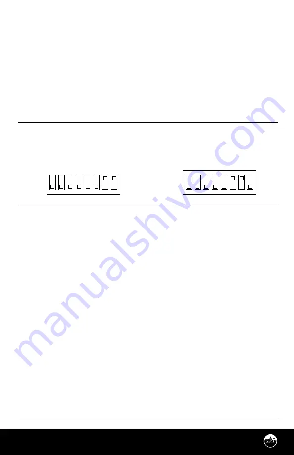
0-10 VDC Output
0-5 VDC Output
4
3
OFF
5
ON
7
ON
2
3
7
8
ON
1
4
5
6
FIGURE 7:
OUTPUT SELECTION SWICHES
OUTPUT SIGNALS
Switches 6, 7, and 8 are used to set the RH output signal. Refer to
FIGURE 7
(below) for switch settings.
HUMIDITY REVERSE ACTING OUTPUT
The output is direct acting and can be changed to reverse acting mode. The output range stays the same
but the corresponding RH value is opposite.
Examples:
Direct Acting (DA)
Reverse Acting (RA)
0-10 V output mode,
0-10 V output mode,
0 V = 0% RH and 10 V = 100% RH
0 V = 100% and 10 V = 0%
To change the transmitter to reverse acting or back to direct acting, set switch 4 to ON to put the unit in
setup mode. After switch 4 is on, turning switch 2 to ON will put the unit in direct/reverse acting mode.
When switch 2 is set to ON, the output can be used to show if the unit is in direct or reverse acting mode.
For direct acting, the output will be 1 V for 0-5 V or 2 V for 0-10 V. For reverse acting the output will be 4 V
for 0-5 V or 8 V for 0-10 V.
With switches 2 and 4 ON, each time switch 5 is set to ON the output will change to reverse acting or direct
acting. To reset the unit to the default setting, toggle both switches 5 and 6 ON then OFF while both
switches 2 and 4 are ON. When all calibration is completed, remember to place the switches back into the
positions that correspond to the output needed as shown in
FIGURE 7
(above).
WIRING INSTRUCTIONS
(Continued)
Connect thermistor/RTD wire leads to controller analog input wires using wire nuts, terminal blocks, or crimp style
connectors. All wiring must comply with local and National Electric Codes.
Note:
When using a shielded cable, be sure to connect only (1) end of the shield to ground at the
controller. Connecting both ends of the shield to ground may cause
a ground loop. When removing the shield from the sensor end, make sure to properly trim the shield to
prevent any chance of shorting.
Note:
If the controller requires a (2) wire input for a RTD, connect the (2) common wires (same color)
together. If the controller requires (3) wires, use (3) individual wires - see
FIGURE 6
(p. 2).


