


6
Operator’s Guide –
Basics
The power amplifier and preset adjustments you’ve just completed, along with the
VGM-
804’s
microprocessor “brain”, make operation as simple as it can be!
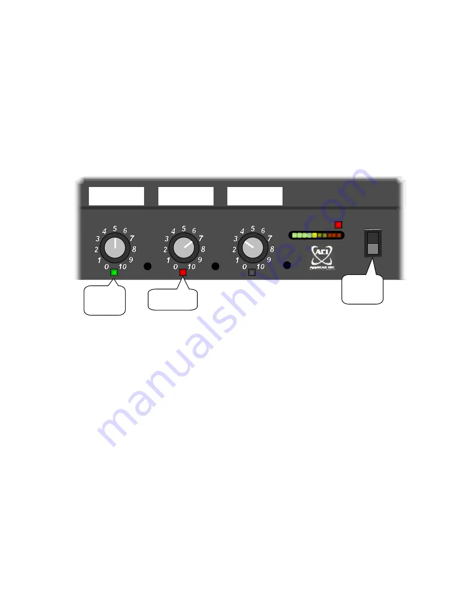
POWER
Switch – At the far right of the panel. Switch ON for use. Many users prefer to plug
the mixer’s AC adapter (as well as the rest of their audio gear) into a switched outlet strip,
leaving the
POWER
switch on. Either way, the first green LED of the level display lights when
the mixer is powered up.
Gain
controls – adjust as needed for good listening levels. You can apply labels on a blank
panel above or below your mixer (as shown above) to describe their actual use. Depending
on the microphones and their placement, about halfway up should provide good usable
level. If needed, adjust the presets (see the previous page). The gating and compression
features mean you’ll do less knob-turning than would be needed with non-automatic mixers.
Gate/Clip
LEDs – under each microphone gain control. Each lights
green
when the mixer
gates that microphone ON. Use these LEDs to identify live mics. For example, during a walk-
though test before the program, have your assistant speak into each mic in turn – the LEDs
show which mixer channels are in use. These LEDs light
red
when their input channels are in
danger of clipping – reduce their gain to remedy this condition.
Clip
LEDs – under the two AUX gain controls. Lights
red
when these channels are near
clipping. To prevent audible distortion, reduce gain should you see the clip indicators light.
If you still need more sound, turn up your power amplifier instead.
The mic and aux input channels all feature sufficient headroom so you should rarely if ever
see red (clipping) lights.
C O M P R E S S
MIC 8
AUX 1
AUX 2
VGM804
Gated
ON
Clipping!
POWER
Switch
Stage Left
CD Player
Phone


