


Automation Components, Inc.
2305 Pleasant View Road | Middleton, WI 53562
Phone:
1-888-967-5224 |
Website:
workaci.com
Page 3
GENERAL INFORMATION
The BACnet MS/TP / Modbus RTU Averaging Series
sensor is designed for use with electronic controllers
in commercial heating and cooling building manage-
ment systems. The ACI BACnet MS/TP / Modbus RTU
Averaging Series sensor monitor the average
temperature in commercial HVAC ductwork and
provides a better average temperature of the air
inside the duct compared to a single point duct
sensor. Averaging sensors are sold in either Copper
or Flexible Averaging variations. The Copper
Averaging sensors include a continuous sensing
element, which covers the entire length of the probe.
The Flexible Averaging sensor has either 4 or 9
sensing points depending on the length. It uses
BACnet MS/TP or Modbus for RTU for physical
connection to a BAS or controller, has dip switches to
set addresses and baud rate, parity and stop bits
(Modbus RTU only), and has on board end-of-line
termination. There is no analog output.
WIRING INSTRUCTIONS
The BACnet MS/TP /Modbus RTU Averaging Series
temperature sensor has a depluggable terminal
block located on the front of the PCB. For ease of
wiring, we recommend removing the block, wiring,
and reattaching before mounting. 16 to 22 AWG
two conductor shielded cable is recommended for
powering the sensors.
ACI recommends using Belden 3105 or compatible
cable for RS-485 communication wiring. This wire has
120 ohm input impendence. The terminal blocks
allow for (1) or (2) wires to be connected in each
position for daisy chaining. Daisy chain the RS-485
wiring and do not use “Star” or “T” wiring. Avoid
running communication wires next to AC line
voltage wires. These can be sources of noise that can
affect signal quality.
PRECAUTIONS
• Remove power before wiring. Never
connect or disconnect wiring with power
applied.
• It is recommended you use an isolated
UL-listed class 2 transformer when powering
the unit with 24 VAC. Failure to wire the
devices with the correct polarity when
sharing transformers may result in damage
to any device powered by the shared
transformer.
• If the 24 VDC or 24VAC power is shared with
devices that have coils such as relays,
solenoids, or other inductors, each coil must
have an MOV, DC/AC Transorb, Transient
Voltage Suppressor (ACI Part: 142583), or
diode placed across the coil or inductor. The
cathode, or banded side of the DC Transorb or
diode, connects to the positive side of the
power supply. Without these snubbers, coils
produce very large voltage spikes when
de-energizing that can cause malfunction or
destruction of electronic circuits.
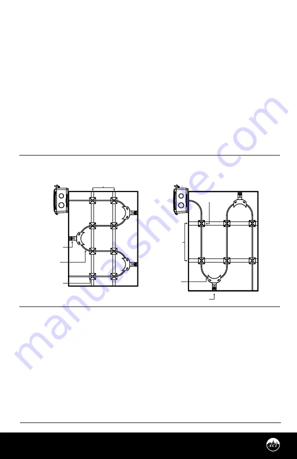
MOUNTING INSTRUCTIONS
Drill a 3/8" (9.53 mm) hole in the duct. Gently uncoil
the copper tubing and insert the averaging
element through the hole until the foam pad is
tight to the duct. The sensor should then be strung
in a criss-cross pattern throughout the duct using
the mounting clips provided - see
FIGURE 5
(P.3)
.
Use a pattern that covers the greatest surface area
of the duct to ensure that there is no stratification.
When bending the copper tubing, be careful that
you use a gradual bend and that you
DO NOT
kink
the copper tubing. Bends should be a minimum of
2” (50.8 mm). Each unit includes nylon wire ties
and mounts for mounting. Optional copper
capillary (ACI Item #
130525)
or universal plastic
mounting clips (ACI Item #
145421
) can be
ordered. Plastic mounting clips will help insulate
the copper sensing element from the metal duct.
The capillary clips help avoid kinks when bending.
When using Flexible averaging, do not cover the
heatshrink that is located throughout the sensor
(sensing points).
Drill pilot holes for the (2) mounting screws. Use the enclosure flange as a guide, or use the
dimensions listed below to measure out. Now fasten and insert (2) screws #8 x 3/4" TEK (provided and
recommended) through the mounting holes in the flange and tighten until the unit is held firmly to
the duct. Make sure the foam pad is tight to the duct to eliminate any possible air leaks.
For optimal temperature measurement, follow these tips:
•
Mount coil horizontal for vertical stratification.
•
Mount coil vertical for horizontal stratification.
•
The sensor must be spread evenly over the full duct.
•
The entire length of the sensor coil must be installed completely inside the duct. Do not have any part of
the sensor exposed to exterior air.
•
When installing the sensor near air-handling units, place the sensor downstream from the fan discharge.
The stratified airstream will be more uniform across the duct cross-section. If the air is not well-mixed, the
reading may be inaccurate.
•
If UV Lights are installed in duct, do not use Flexible Averaging. There is no UV protectant on outer cable
jacket. Copper averaging must be used in this situation.
BACnet MS/TP and Modbus RTU
INTERFACE
(Continued)
ACI’s Modbus RTU sensors are slave devices. Only
one master is connected to the bus and several
slave nodes are connected to the same trunk. The
Master initiates communication. The slave nodes
only respond to a request from the Master. Slave
nodes do not communicate with each other.
Each branch must have all devices connected with
(+) connected to (+) and (-) connected to (-). If a
shielded cable is used, this is not to be connected
to the devices. The shield cable should only be
connected on one end to earth ground, usually at
the controller. The start and end of each branch
should have a termination resistor at the device
level or at the controller.
Each device must be configured for the correct
baud rate and have a unique address in each
branch. The baud rate for the branch is set by the
controller. This product has auto-baud for ease of
network configuration but setting the baud rate
using the DIP switches is recommended.
Note:
Auto-baud feature does not function when
Modbus is the selected protocol.
BAUD RATE SELECTION
By default, BACnet Protocol and Auto-Baud is
factory set. If the sensor is field adjusted for
Modbus RTU, the baud rate should be selected at
this time to match the Master configuration. If
Modbus RTU protocol is selected it is
recommended the sensor unique address is
selected at this time. Switches 8-10 are used to
set the BACnet and Modbus baud rate. Refer to
TABLE 3
for switch settings. Where (0) is OFF and
(1) is ON. If the system’s baud rate is known, it is
recommended to set the specific baud rate to
match the system.
If the device is powered when
a change is made, the device must be power
cycled or reset for changes in baud rate to be
made.
BACnet MS/TP and Modbus RTU INTERFACE
The BACnet Master-Slave/Token-Passing (MS/TP) and Modbus Remote Terminal Unit (RTU) data link
protocol uses EIA-485 as a two-wire, daisy chain network. A branch is a discrete chain of devices connected
to a controller. The max number of devices per segment is 32, as per the BACnet and Modbus
specifications. 4000 ft (1219.2 m) is the maximum recommended length for a segment, which includes all
devices from the controller to the last device in the daisy chain.
BACnet or Modbus RTU protocol selection is done via SW4 switch. Place dipswitch #4 to the OFF position
for BACnet and the ON position for Modbus. Refer to
FIGURE 6
.
ACI’s BACnet sensors are master devices. Only master nodes are allowed to send and receive tokens on the
MSTP network.
VERTICAL COILING
OPTIONAL COPPER OR
PLASTIC CAPILLARY CLIP
WIRE TIE MOUNT
HANGER STRIPS
OPTIONAL COPPER OR
PLASTIC CAPILLARY CLIP
WIRE TIE MOUNT
HANGER STRIPS
FIGURE 5:
HORIZONTAL AND VERTICAL COILING
HORIZONTAL COILING
MIN. BEND
RADIUS 2” (50.8 mm)
MIN. BEND
RADIUS 2” (50.8 mm)
EOL TERMINATION RESISTANCE
SELECTION
RS-485 requires that the last device in a chain
have a termination resistor. This is controlled
using a jumper in the EN (enabled) position
marked on
FIGURE 7
. When the jumper is set to
EN (enabled), a 120Ω resistance is added in
parallel to the data line. When the jumper is set to
DIS (disable), the resistance is not added. By
default, the jumper is placed in the DIS (disabled)
position.
RESET
The reset button can be used to reset the device
without disconnecting power. The location of
this button is shown in
FIGURE 2 (P.1).
Version: 2.0
I0000932


