background image

Electric Chain Hoists (Single Brake) 

Model NECH 

PAGE: 76 

NECH-0214 

ACI Hoist & Crane | 2721 NE 4th Ave Pompano Beach, FL 33064| 954.367.6116 

Visit WWW.ACIHOIST.COM for the most current information 


11.9


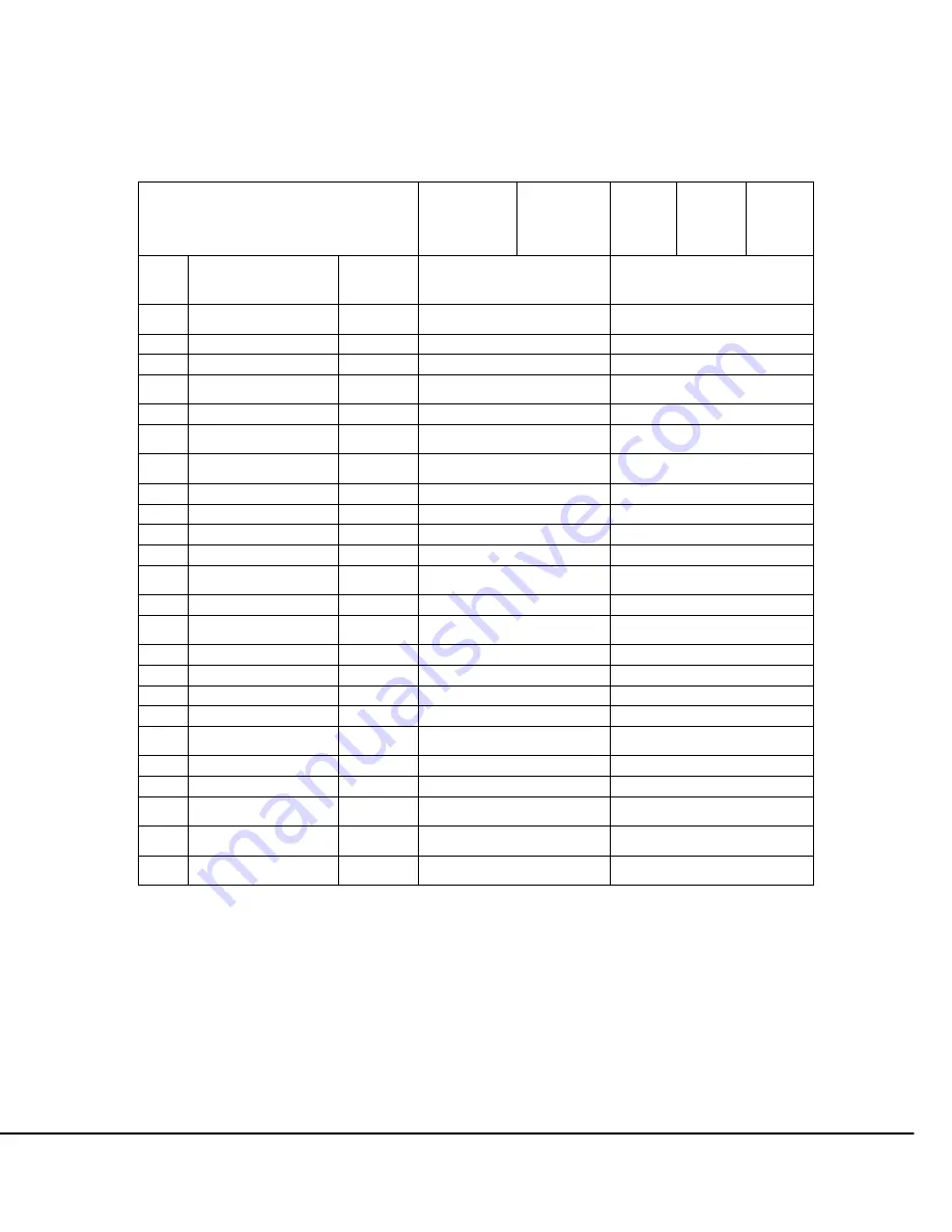
Parts List: Gear Box Assembly 

Table 11.9.1 

Gear Box Assembly Parts List: 6.3-7.1 mm  


Hoist Model 


NECH-

00526 

NECH-

02013 

NECH-

01016 

NECH-

01026 

NECH-

04008  

NECH-

04013 

NECH-

02016  

NECH-

02013 

NECH-

04008  

NECH-

06009  

 
Item 

 
Spare Parts Name 


Quantity 

0.5 TO 1 TON                 

6.3mm chain 

1 TO 3 TON                                             

7.1mm chain 

1


Deep groove ball 
bearing


1


KD4-001


KD4-101


2


circlip for shaft


1


KD4-002


KD4-102


3


Output gear


1


KD4-003


KD4-103


4


Deep groove ball 
bearing


1


KD4-004


KD4-104


5


Gear-gear shaft


1


KD4-005


KD4-105


6


Deep groove ball 
bearing


1


KD4-006


KD4-106


7


Deep groove ball 
bearing


1


KD4-007


KD4-107


8


Oil seal


1


KD4-008


KD4-108


9


Chain wheel


1


KD4-009


KD4-109


10


Oil seal


1


KD4-010


KD4-110


11


Output shaft assembly


1


KD4-011


KD4-111


12


Deep groove ball 
bearing


1


KD4-012


KD4-112


13


Bearings fixed ring


1


KD4-013


KD4-113


14


Deep groove ball 
bearing


1


KD4-A014


KD4-A114


15


Circlip for hole


1


KD4-015


KD4-115


16


Spring straight pins


2


KD4-016


KD4-116


17


Spring washer


3


KD4-017


KD4-117


18


socket head cap screws


3


KD4-018


KD4-118


19


Reduction gear fixed 
axis


1


KD4-019


KD4-119


20


Bearing


2


KD4-020


KD4-120


21 

Dual gears


1


KD4-021


KD4-121


22 

Reduction gear fixed 
frame 

1


KD4-022 

KD4-122 

23 

Reduction gear fixed 
stator 

1


KD4-023 

KD4-123 

24 

Cross Recessed 
Countersunk Screw 

1


KD4-024 

KD4-124 


Summary of Contents for NECH Series

Page 1: ...hased ELECTRIC CHAIN HOIST Single Brake OPERATION MANUAL This operation manual is intended as an instruction manual for trained personnel who oversee installation maintenance repair etc ELECTRIC CHAIN HOISTS Single Brake Model NECH ACI Hoist Crane 2721 NE 4th Ave Pompano FL 33064 954 367 6116 Scan QR Code with ...

Page 2: ...Electric Chain Hoists Single Brake Model NECH PAGE 2 NECH 0214 ACI Hoist Crane 2721 NE 4th Ave Pompano Beach FL 33064 954 367 6116 Visit WWW ACIHOIST COM for the most current information ...

Page 3: ...lation of Hoist with Trolley 17 4 2 2 Installation of Trolley Hoist on the Beam 20 4 2 3 Connecting Power Supply to Hoist 21 4 2 4 Load Chain 21 4 3 Prior To Operation 23 4 3 1 Motor Phasing 23 4 3 1 Trolley Motor Phasing 24 4 4 Testing Limit Switches 24 4 5 Hoist Load Test 25 5 0 OPERATION 26 5 1 General Safety 26 5 1 1 General DO s and DO NOT S 27 5 2 Safety Rules before Operating the Hoist 27 5...

Page 4: ...intenance 49 7 3 Chain Replacement 49 7 4 Hoist Motor Brake Adjustment 51 7 5 Hoist Motor Brake Disassembly 53 8 0 TROUBLESHOOTING 55 9 0 WIRING DIAGRAMS 57 10 0 DIMENSIONS SPECIFICATIONS 58 10 1 Table of Specifications 58 10 2 Hoist Specifications 59 10 3 Hoist Dimensions 59 11 0 EXPLODED VIEWS PARTS LISTS 62 11 1 Exploded View Motor Body Assembly 62 11 2 Parts List Motor and Body Assembly 63 11 ...

Page 5: ...e factory If an inspection reveals that the problem is caused by defective workmanship or material repairs will be made without charge and the product will be returned with the shipping prepaid Excluded Items This warranty does not cover Deterioration caused by normal wear abuse chemical or abrasive actions improper maintenance or excessive heat Problems resulting from repairs modifications or alt...

Page 6: ...ation or maintenance information which is important but not directly hazard related This manual contains important information to help you properly install operate and maintain the ACI Electric Chain Hoist for maximum performance and safety purposes Please study the contents thoroughly before putting the hoist in operation Only through proper installation application of correct operating procedure...

Page 7: ...o not apply Record hoist serial number on the front cover of this manual for identification and future reference to avoid referring to the wrong manual for information or instructions on installation operation inspection maintenance or parts It is the responsibility of the owner user to install inspect test maintain and operate a hoist in accordance with ASME B30 16 Safety Standard for Overhead Ho...

Page 8: ...ger of electric shock 2 3 Safe Hoisting and OSHA Compliance The following is a list of the minimum that should be done to keep the hoists and cranes operating properly safely and within OSHA regulations The following should be done to all hoisting equipment including hand and ratchet hoists 1 Operator Training Like forklifts and trucks operator training is required for every operator of hoisting e...

Page 9: ...f your equipment OSHA 1910 179 j 2 ANSI B30 16 Based on use and environment ACI can provide these inspections anywhere from a monthly to an annual basis The inspections are designed to maintain the equipment and reduce the long term maintenance costs 7 Records Dated inspection records shall be kept for inspections and maintenance ANSI B30 16 16 2 1 1 2 Records should be kept where easily available...

Page 10: ...sonnel from serviceplatform and path of load WHILE OPERATING DO NOT Lift more than rated load Lift people or loads over heads of people WARN personnel of approachingloads Make side pulls Lift all loads vertically Use limit switches as routine operatingstops THESE ARE EMERGENCY DEVICES ONLY Operate if rope or chain slips from groves or sprockets REPLACE in grooves or sprockets before continuing ope...

Page 11: ...the same voltage frequency and phase that are specified on the hoist and trolley nameplate Every hoist should be equipped with the following standard accessories One Chain Container Control Cable One Control Station Before using the hoist fill in the information below Model Number Serial Number Purchase Date Installation MUST be performed by a qualified person in accordance with ACI Hoist Crane Se...

Page 12: ...eave Empty for Single Speed Hoist Speed FPM 3 0 GENERAL DESCRIPTION FEATURES 3 1 Model Numbering NECH H 010 26 V 15 Lift ft 10 10 ft 15 15 ft Etc Suspension H Hook Mounted L Lug Mounted M With Motorized Trolley P With Standard Push Trolley G With Geared Trolley Capacity 005 Ton 010 Ton 020 1 Ton 040 2 Ton 060 3 Ton 100 5 Ton 150 7 Ton 200 10 Ton 300 15 Ton 400 20 Ton 600 30 Ton 700 35 Ton Type NEC...

Page 13: ...or the most current information Ensure the motor comes to a complete stop before reversing the direction 3 2 Pendant Control Pendant stations are provided fully assembled When using a pendant control depress the up button to raise the hoist or the down button to lower the hoist as shown in Figure 3 5 1 below To stop motion release the buttons Figure 3 2 1 ...

Page 14: ... Hoists Single Brake Model NECH PAGE 14 NECH 0214 ACI Hoist Crane 2721 NE 4th Ave Pompano Beach FL 33064 954 367 6116 Visit WWW ACIHOIST COM for the most current information Push Button Station Dimensions Table 3 2 2 ...

Page 15: ...nd the crane runway remains energized because of other cranes operating on the same runway stops or a signal person s located full time at a visual vantage point for observing the approach of active crane s shall be provided to prohibit contact by the active crane s with the idle crane If personnel will be required to work on the runway during installation a guard or barrier shall be installed bet...

Page 16: ...er and electricity If the hoist has a trolley check that the crane bridge beam or monorail beam is level straight and clean Check that trolley stops are installed or install trolley stops at the open end or ends of the beam to prevent the trolley from traveling off the beam Trolley stops that engage trolley wheels are not recommended Check that trolley stops will prevent overhanging parts of the h...

Page 17: ...with Trolley If the trolley hoist is mounted on a skid do not remove it immediately The skid will hold the trolley hoist unit in an upright position until assembled on the crane or monorail Figure 4 2 1 1 Figure 4 2 1 2 1 Remove cotter pin from trolley shaft dowel pin Spacer Pin and slide suspension shaft out of side plate S refer to Figures 4 2 1 3 and 4 2 1 4 Suspension Shaft Spacer Pin Side Pla...

Page 18: ... beam where the trolley is to be installed 3 Slide one stack of inner adjusting spacer over the suspension shaft Total width should be about half of the flange width of the beam Then insert suspension shaft into suspender T refer to Figure 4 2 1 5 Figure 4 2 1 5 4 Slide same size of inner adjusting spacer stack next to the suspender T and install side plate S to the suspender shaft refer to Figure...

Page 19: ... suspension shaft Figure 4 2 1 7 7 Make sure both side plates are spread fully outward and measure dimension A Dimension A must be 5 32 4 mm greater than B refer to Figure 4 2 1 7 8 Rearrange spacers if necessary to achieve proper spacing Distribute washers equally so that the hoist will be centered between trolley side plates and under beam 9 After obtaining the proper adjustment secure the shaft...

Page 20: ...y removing the spacer pin from the suspension shaft hole A Then insert it into hole B Insert cotter pin in the spacer pin to fix it in place On geared and motorized trolleys it is recommended that the side with the plain wheels be removed 4 Spread side plate G and side plate S apart Lift the trolley up to the beam keep both sides of the wheel and beam at the same level 5 Support one side plate the...

Page 21: ...g diagram on page 65 4 2 4 Load Chain After installation of hoist to the beam check the load chain utilizing the following steps 1 Check the location of the welding points on the chain All welds should be inline refer to Figure 4 2 4 1 2 Check for twists and kinks in the chain refer to Figure 4 2 4 2 3 Raise the load block without a load to within three feet of driving load sheave 4 Check the dire...

Page 22: ...e it in place with the chain container pins and cotter pins Orient the container as shown in Figure 4 2 4 3 3 Place loose end of chain with chain stop into the container The loose end of the chain should flow into the container DO NOT use a chain container with a storage capacity less than the lift length on the hoist refer to Table 4 2 4 1 Table 4 2 4 1 Chain Bag Dimensions Model Number Chain Len...

Page 23: ... and or motor phasing do the following MOMENTARILY activate the UP button of the hoist control device and observe the direction of the hook motion If the direction of the hook travel matches the direction marking of the hoist control device button activated then the hoist motor is properly phased If the direction of the hook travel does not match the direction marking of the hoist control device b...

Page 24: ...block with approximately nine to fifteen 9 15 links of load chain extending beyond the chain guide on the unloaded side of the hoist It is recommended that the lower limit device be set to prevent the load block from resting on the floor and allowing the load chain to go slack If adjustment of the lower limit device is required refer to the Limit Switches section of this manual To check upper limi...

Page 25: ...ould still be test operated as follows with a load on the hoist hook 1 Attach a load to the hoist hook Load shall not exceed the rated load capacity of the hoist 2 Before lifting the load operate the hoist in the raising direction to take any slack out of the hoist load chain 3 Raise the load a few inches and stop the hoist If brakes stop and hold the load continue raising and lowering the load se...

Page 26: ...es that can make an operator aware of dangerous practices to avoid and precautions to take for his or her own safety and the safety of others Observance of these rules in addition to frequent examinations and periodic inspection of the equipment may save injury to personnel and damage to equipment Hoist operators SHALL be required to read the operation section of this manual the DANGERS WARNINGS C...

Page 27: ...operate inspect maintain or repair the hoist DO NOT operate a hoist that is damaged or has any actual or suspected mechanical or electricalmalfunction DO NOT use the chain any part of the hoist or the load block and hook as a ground for welding 5 2 Safety Rules before Operating the Hoist Be familiar with all operating controls of the hoist Be familiar with the operation procedures of this manual t...

Page 28: ... load Confirm that when the load is lifted it will clear all material machinery or other obstructions in the area 5 3 Safety Rules for Operating the Hoist DO NOT engage in any activity that will divert the attention of the operator DO NOT lift lower or transport a load and hoist until the operator and all other personnel are clear of the load and the path of the load Confirm that the load a hoist ...

Page 29: ...ion the hoist load block and hook above head level for storage when the hoist is not in use 5 5 Safety Rules before Each Shift Visually inspect the load chain for nicks gouges and any type of deformation or damage to the load chain Check for lubrication of load chain Visually inspect the hooks for nicks gouges deformation of the throat opening and wear on saddle or load bearing point and twisting ...

Page 30: ...ensive knowledge training and experience has successfully demonstrated the ability to solve or resolve problems relating to the subject matter and work Definitions of service from ASME B30 16 are as follows Normal Service service which involves operation of the hoist with randomly distributed loads within the rated load limit or uniform loads less than 65 of rated load for not more than 25 of the ...

Page 31: ...laced and other loose material shall be removed o All equipment used in the maintenance repair or inspection work shall be removed Warning signs barriers and guards shall be removed only by authorized personnel Lock and tag on the main switch disconnect of the hoist crane or lifting device shall be removed only by the person that locked and tagged the main switch originally or an authorized person...

Page 32: ...ekly to monthly Severe service daily to weekly PERIODIC INSPECTION Periodic inspections are visual and audio inspections by designated personnel making records of external conditions to provide the basis for a continuing evaluation of the hoist and its components If the external inspection indicates the need some disassembly may be required to make a more detailed inspection and examination Nomina...

Page 33: ...aired and cleared the hoist for operation Control Devices Check that the travel motions match with the control device markings When checking hoist travel motion always usethe lifting UP control first Repair or replace as required Upper Limit Switch Check that the upper limit switch stops the lifting motion of the hoist load block before striking any part of the hoist or crane Repair or replace as ...

Page 34: ...original dimensions Measure hook throat opening from metal to metal of the hook as shown by dimension g in Figure 6 4 1 DO NOT measure from latch to metal Hook must be replaced when throat opening measurement has increased 5 over the original throat opening dimension of a new hook Refer to Table 6 4 2 for original dimensions and replacement dimensions for throat openings of standard hooks specifie...

Page 35: ...rom the plane of the unbent hook requires the replacement of the hook A hook latch when required that is missing shall be replaced A hook latch when required that is inoperative shall be repaired or replaced Hooks having damage from chemicals corrosion or deformation shall be repaired or replaced Damage in the form of cracks nicks and gouges may be repaired by a designated person by grinding longi...

Page 36: ...d in either raising or lowering directions which can cause damage to the hoist Figure 6 5 1 When the highest position is reach the limit actuator limit spring on the load chain above the hook block trips the limit lever see Figure 6 5 2 Never weld handles or other attachments to the hook Heat applied to the hook will alter the original heat treatment of the hook material and reduce the strength of...

Page 37: ... to be used on a routine basis to stop travel of hook block or to shut off the hoist The hoist lower limit device is set at the factory to stop lower travel of the load block with approximately 10 to 15 links of load chain extending beyond the chain guide on the unloaded side of the hoist It is recommended that the lower limit device be set to prevent the load block from resting on the floor and a...

Page 38: ...the chain container is used the free end of the chain is attached to the hoist body as shown in Figure 6 5 5 Depending on the hoist size and capacity install the chain stopper approximately 7 to 12 links from the free end and make sure the chain remains free of twists Figure 6 5 5 In some other hoist models the free end of the chain is not attached to the hoist body and the chain stopper is instal...

Page 39: ...e detailed inspection is performed to determine that the chain can be used or the chain is replaced Detailed inspection procedures are outlined below These procedures also apply to scheduled frequent and periodic inspections The load chain should be inspected during scheduled frequent and periodic inspections or if the daily visual inspection by the operator indicates a more detailed inspection is...

Page 40: ...of wear by subtracting themeasurement of the unworn section from the measurement of the worn section If the result amount of wear is greater than the amount specified in the Allowable Chain Wear Table 6 6 1 then the chain has elongated beyond the maximum allowable length and must be replaced Table 6 6 1 Allowable Chain Wear Hoist Capacity Number of Pitches to Measure Max Wear Limit 0 25 0 5 11 0 1...

Page 41: ...pection During daily frequent or periodic inspections the hoist braking system should be checked by operating the hoist in the lifting and lowering directions without a load on the hook and stop the hook motion to check operation of the hoist braking system The hook s drift should not exceed inch in either direction If the hook drifts exceeds 1 4 inch the motor brake requires adjustment or the lin...

Page 42: ... service should be checked without a load on the hook by the operator At the start of each shift or the first time the hoist is to be operated during each shift The trolley brake should be checked during scheduled frequent and periodic inspections During daily frequent or periodic inspections the trolley brake should be inspected as follows Operate the trolley in both travel directions without a l...

Page 43: ...ve any lining dust that has accumulated on brake parts see Figure 6 8 2 Figure 6 8 2 Check for loose electrical connections or broken wires Repair or replace as required Check thickness of brake pad Replace the brake pad if worn to a thickness of 0 14 inch 3 6 mm or less Trolley brake is not adjustable After the brake is inspected carefully place the stator and brake components into the motor fram...

Page 44: ... mandatory and must be followed SHOULD indicates that the rule is a recommendation the advisability of which depends on the facts in each situation 6 9 2 Operational Test All altered or repaired hoists or hoists that have not been used within the past 12 months SHALL be tested by the owner user before being placed in operational service The operational test is performed without a load on the hook ...

Page 45: ...ey motion If the direction of the trolley travel matches the direction marking of the trolley control device button activated example the trolley direction is EAST when the trolley EAST control device button is activated the trolley motor is properly phased If the direction of the trolley travel does not match with the direction marking of the trolley control device button activated the trolley mo...

Page 46: ...vice The load test shall be conducted under the direction of a designated person and a record of the test should be made The test load applied to the hoist shall be at least equal to the rated load capacity of the hoist or greater as approved by the hoist manufacturer Functions to be performed during the load test include Operation of control devices Lifting and lowering Operation of brakes Load t...

Page 47: ...nal information is required in reference to adjustment maintenance or identification of parts contact ACI Hoist Crane or the distributor of the hoist 7 1 Lubrication All moving parts of the hoist or trolley for which lubrication is specified should be inspected checked and lubricated on a regular basis This section applies to the hoist and trolley only If the hoist is installed as part of a crane ...

Page 48: ... the oil more frequently for heavy service or as required by operating environment The hoist is shipped from the factory with the correct quantity and type of oil in separate container s or use of engine oil with the same grade of ISO VG 46 or equivalent is authorized For hoist gear box oil capacity refer to Table 7 1 1 1 Table 7 1 1 1 Gear Box Oil Capacity Hoist Capacity Tons Gear Box Oil Capacit...

Page 49: ...ss utilized to clean the chain must not damage the chain any solution used shall be acid free Replacement chain should be stored in a manner to prevent damage or deterioration to the chain During installation of chain care should be exercised to avoid dragging the chain in dirt or around objects that will scrape nick cut crush or induce sharp bends in the chain Load chain links articulate slowly u...

Page 50: ...2 3 1 18 7 16 2 5 3 5 7 5 1 34 15 32 Capacity measured in tons All other measurements in inches 7 Remove the hook block assembly and actuator from the old chain and attach them to the replacement chain at the end which was just run through the hoist Depending on hoist configuration install limit actuator chain spring and stopper on the other end of the chain or connect the end chain to the hoist b...

Page 51: ...e downtime it is recommended to check the motor brake lining and adjustment at regular intervals Inspection and adjustment of the motor brake requires removal of the motor brake unit from the hoist as an assembly But first be sure that the power is off the hoist is unloaded and the load chain is secured Refer to Figure 10 1 1 for Motor and Body Parts List 1 Loosen and remove socket head cap screw ...

Page 52: ...t gap is 0 02 Adjustment should not be necessary until the gap is 0 031 Adjustment of the brake gap is accomplished by turning the adjustment nut in the center of the motor cover as follows 1 Remove the rubber cover see Figure 7 4 4 Figure 7 4 4 2 Bend the tab of the lock washer away from the adjusting nut so that the adjusting nut can be rotated see Figure 7 4 5 Adjusting Nut Lock Washer Figure 7...

Page 53: ...nut clockwise tightening to line up the tab with the slot 6 If the proper brake adjustment cannot be achieved disassemble the motor brake and inspect all motor brake parts Replace the brake pad if necessary 7 5 Hoist Motor Brake Disassembly 1 Loosen and remove socket head cap screw and spring washers securing the motor shell see Figure 7 4 1 2 Carefully pull the motor brake unit out of the hoist s...

Page 54: ... Figure 7 5 2 Rotor Assembly 8 Inspect all parts Braking surfaces should be clean free of grease oil and should not be glazed Measure brake gap see Figure 7 4 7 and brake lining see Figure 7 5 3 and compare the measurement with the values listed in Table 6 7 1 Replace the brake pad assembly if the measurement is smaller than thereplace limit Figure 7 5 3 9 After the bake is properly adjusted and i...

Page 55: ...eck voltage and frequency or power supply They must match with the data on the nameplate Improper loose or broken wire connection Check wiring connections Check connections in pushbutton station and limit switches Brake does not release Check connections and lead wires Check connections in control devices Control transformer damaged Check transformer fuses coil and open winding Motor burned out Re...

Page 56: ...torque Hoist motor overheats Excessive load Reduce load to the rated load shown on the nameplate Excessive duty cycle Reduce frequency of lift Excessive jogging Reduce frequency of jogs Wrong voltage or frequency Check voltage and frequency rating on motor data plate against the power supply Damaged motor or worn bearings in motor or hoist frame Disassemble the hoist and inspect for worn or damage...

Page 57: ...t Crane 2721 NE 4th Ave Pompano Beach FL 33064 954 367 6116 Visit WWW ACIHOIST COM for the most current information 9 0 WIRING DIAGRAMS Figure 9 1 Electric Chain Hoists Single Brake PAGE 57 Model NECH NECH 0214 ...

Page 58: ...hain hoists Table 10 1 1 Item Specification Range of Working Humidity 85 or less Range of Working Temperature F 4 to 104 Protection Class Hoist Nema 3 Power Supply 3 Phase 240 480 V 60 Hz Noise Degree dB Single Speed Hoist 80 Double Speed Hoist 81 If working temperature and humidity are over the values of the table contact Distributer The hoists are design to vertically lift loads in normal atmosp...

Page 59: ... 12 8 6 4 254 3 NECHH 06009 3 9 2 6 4 3 2 187 3 NECHH 06017 2 17 4 12 8 6 4 289 5 NECHH 10010 2 10 4 12 8 6 4 333 7 1 2 NECHH 15007 3 7 4 12 8 6 4 390 10 NECHH 20010 4 10 2X4 32 8 12 8 661 15 NECHH 30007 6 7 2X4 32 8 12 8 842 20 NECHH 40005 8 5 2X4 32 8 12 8 1025 25 NECHH 50005 8 5 2X4 32 8 12 8 1069 30 NECHH 60003 10 3 2X4 32 8 12 8 2116 35 NECHH 70003 10 3 2X4 32 8 12 8 2535 To complete your Mod...

Page 60: ...8 1 4 5 5 6 9 1 2 NECHM 04013 28 6 20 5 10 2 ɸ 1 9 1 6 1 2 ɸ 1 9 1 6 9 3 5 4 5 6 9 1 2 NECHM 04026 26 8 24 2 11 6 ɸ 1 9 1 6 1 2 ɸ 1 9 1 6 9 3 5 4 5 6 9 1 3 NECHM 06009 33 5 20 5 10 2 ɸ 2 3 1 9 1 4 ɸ 2 3 1 9 10 4 6 2 5 6 9 1 3 NECHM 06017 33 1 24 2 11 6 ɸ 2 3 1 9 1 4 ɸ 2 3 1 9 10 4 6 2 5 6 9 1 5 NECHM 10010 36 5 24 2 11 6 ɸ 2 4 1 9 1 7 ɸ 2 3 1 9 11 7 7 0 5 6 9 1 7 5 NECHM 15007 43 7 24 2 11 6 ɸ 3 3...

Page 61: ... 10 3 4 Hoist Dimensions Cap Ton Model Number H A B D E I J K L M N P Q R T 15 NECHM 30007 48 1 24 8 12 4 42 1 21 1 ɸ2 1 ɸ2 1 ɸ4 7 3 8 3 5 3 1 36 5 22 5 6 9 1 20 NECHM 40005 54 4 24 8 12 4 49 6 24 8 ɸ2 8 ɸ2 8 ɸ5 9 4 5 3 5 3 7 43 5 29 5 6 9 1 25 NECHM 50005 54 4 24 8 12 4 49 6 24 8 ɸ2 8 ɸ2 8 ɸ5 9 4 5 3 5 3 7 43 5 29 5 6 9 1 30 Ton 35 Ton Table 10 3 5 Hoist Dimensions Cap Ton Model Number H A B E I ...

Page 62: ... Model NECH PAGE 62 NECH 0214 ACI Hoist Crane 2721 NE 4th Ave Pompano Beach FL 33064 954 367 6116 Visit WWW ACIHOIST COM for the most current information 11 0 EXPLODED VIEWS PARTS LISTS 11 1 Exploded View Motor Body Assembly Figure 11 1 ...

Page 63: ... 006 KD1 106 7 Socket head cap screw 4 KD1 007 KD1 107 8 Spring washer 4 KD1 008 KD1 108 9 Motor cover 1 KD1 009 KD1 109 10 Rotor washer 1 KD1 010 KD1 110 11 Plate spring 4 KD1 011 KD1 111 12 Brake pad assembly 1 KD1 012 KD1 112 13 Brake spring 1 KD1 013 KD1 113 14 Brake magnet locking sleeve 1 KD1 014 KD1 114 15 Brake magnet split ring 1 KD1 015 KD1 115 16 Brake magnet coil 1 KD1 016 KD1 116 17 P...

Page 64: ...ush 1 KD1 032 KD1 132 33 Sleeve bolt 4 KD1 033 KD1 133 34 Dowel pin 2 KD1 034 KD1 134 35 Gasket C 1 KD1 035 KD1 135 36 Middleware 1 KD1 036 KD1 136 37 Hex screw washer 2 KD1 037 KD1 137 38 Hex screw 2 KD1 038 KD1 138 39 Dowel pin 2 KD1 039 KD1 139 40 Spring washer 6 KD1 040 KD1 140 41 Socket head cap bolt 6 KD1 041 KD1 141 42 Gasket D 1 KD1 042 KD1 142 43 Eye bolt 1 KD1 043 KD1 143 44 Eye bolt gas...

Page 65: ...rclip for hole 1 KD1 205 6 Deep groove ball bearing 1 KD1 206 7 Socket head cap screw 4 KD1 207 8 Spring washer 4 KD1 208 9 Motor cover 1 KD1 209 10 Rotor washer 1 KD1 210 11 Plate spring 4 KD1 211 12 Brake pad assembly 1 KD1 212 13 Brake spring 1 KD1 213 14 Brake magnet locking sleeve 1 KD1 214 15 Brake magnet split ring 1 KD1 215 16 Brake magnet coil 1 KD1 216 17 Plate spring 1 KD1 217 18 Rotor ...

Page 66: ...ket B 1 KD1 230 31 Bottom plate for gear box 1 KD1 231 32 Upper hook bearing bush 1 KD1 232 33 Sleeve bolt 4 KD1 233 34 Dowel pin 2 KD1 234 35 Gasket C 1 KD1 235 36 Middleware 1 KD1 236 37 Hex screw washer 2 KD1 237 38 Hex screw 2 KD1 238 39 Dowel pin 2 KD1 239 40 Spring washer 6 KD1 240 41 Socket head cap bolt 6 KD1 241 42 Gasket D 1 KD1 242 43 Eye bolt 1 KD1 243 44 Eye bolt gasket 1 KD1 244 45 G...

Page 67: ...ists Single Brake Model NECH PAGE 67 NECH 0214 ACI Hoist Crane 2721 NE 4th Ave Pompano Beach FL 33064 954 367 6116 Visit WWW ACIHOIST COM for the most current information 11 3 Exploded View Chain Assembly Figure 11 3 1 ...

Page 68: ...2 3 Slotted countersunk head screws 1 KD5 003 KD5 103 4 Chain Guide 1 KD5 004 KD5 104 5 Pulley Shaft 1 KD5 005 KD5 105 6 Oriented Pulley 1 KD5 006 KD5 106 7 Spring Washer 4 KD5 007 KD5 107 8 socket head cap screws 4 KD5 008 KD5 108 9 split pin 1 KD5 009 KD5 109 10 Limit switches connecting shaft 1 KD5 010 KD5 110 11 Axis of the Middle pin 1 KD5 011 KD5 111 12 Middle pin of guide frame 1 KD5 012 KD...

Page 69: ...n 2 KD5 202 KD5 302 3 Slotted countersunk head screws 1 KD5 203 KD5 303 4 Chain Guide 1 KD5 204 KD5 304 5 Pulley Shaft 1 KD5 205 KD5 305 6 Oriented Pulley 1 KD5 206 KD5 306 7 Spring Washer 4 KD5 207 KD5 307 8 socket head cap screws 4 KD5 208 KD5 308 9 split pin 1 KD5 209 KD5 309 10 Limit switches connecting shaft 1 KD5 210 KD5 310 11 Axis of the Middle pin 1 KD5 211 KD5 311 12 Middle pin of guide ...

Page 70: ...oists Single Brake Model NECH PAGE 70 NECH 0214 ACI Hoist Crane 2721 NE 4th Ave Pompano Beach FL 33064 954 367 6116 Visit WWW ACIHOIST COM for the most current information 11 5 Exploded View Hook Assembly Figure 11 5 1 ...

Page 71: ...Thust ball bearing 1 KD2 003 KD2 103 KD2 203 4 Lower hook split ring 2 KD2 004 KD2 104 KD2 204 5 Lower hook locking sleeve 1 KD2 005 KD2 105 KD2 205 6 Socket head cap screw 2 KD2 006 KD2 106 KD2 206 7 Lower hook swivel shell 2 KD2 007 KD2 107 KD2 207 8 Chain limit spring 1 KD2 008 KD2 108 KD2 208 KD2 208 2 9 Chain 10 ft standard 10 Self locking nut 2 KD2 010 KD2 110 KD2 210 11 Slotted spring pins ...

Page 72: ...4 KD2 504 5 Lower hook locking sleeve 1 KD2 305 KD2 505 6 Socket head cap screw 2 KD2 306 7 Lower hook swivel shell 2 KD2 307 8 Chain limit spring 1 KD2 308 KD2 308 2 KD2 508 2 9 Chain 10 ft standard 10 Self locking nut 2 KD2 310 11 Slotted spring pins 1 KD2 311 KD2 511 12 Outer hexagonal bolt 4 KD2 312 KD2 512 13 Lower load block shell 2 KD2 313 KD2 513 14 Needle bearing 2 KD2 314 KD2 514 15 Lowe...

Page 73: ...s Single Brake Model NECH PAGE 73 NECH 0214 ACI Hoist Crane 2721 NE 4th Ave Pompano Beach FL 33064 954 367 6116 Visit WWW ACIHOIST COM for the most current information 11 7 Exploded View 3 part Hook Assembly Figure 11 5 2 ...

Page 74: ... 6 KD3 308 KD3 708 9 Spring washer 6 KD3 309 KD3 709 10 Stent motherboard under 1 KD3 310 KD3 710 11 Chain guiding for inlet and outlet 1 KD3 311 KD3 711 12 Chain 30 feet standard 13 Limit spring 1 KD3 312 KD3 712 14 Guide chain body 1 KD3 313 KD3 713 15 Chain bolt 1 KD3 314 KD3 714 16 Chain locking block 1 KD3 315 KD3 715 17 Locking block of gasket 1 KD3 316 KD3 716 18 Hex slotted nut 1 KD3 317 K...

Page 75: ...sts Single Brake Model NECH PAGE 75 NECH 0214 ACI Hoist Crane 2721 NE 4th Ave Pompano Beach FL 33064 954 367 6116 Visit WWW ACIHOIST COM for the most current information 11 8 Exploded View Gear Box Assembly Figure 11 8 1 ...

Page 76: ... 004 KD4 104 5 Gear gear shaft 1 KD4 005 KD4 105 6 Deep groove ball bearing 1 KD4 006 KD4 106 7 Deep groove ball bearing 1 KD4 007 KD4 107 8 Oil seal 1 KD4 008 KD4 108 9 Chain wheel 1 KD4 009 KD4 109 10 Oil seal 1 KD4 010 KD4 110 11 Output shaft assembly 1 KD4 011 KD4 111 12 Deep groove ball bearing 1 KD4 012 KD4 112 13 Bearings fixed ring 1 KD4 013 KD4 113 14 Deep groove ball bearing 1 KD4 A014 K...

Page 77: ...203 KD4 303 4 Deep groove ball bearing 1 KD4 204 5 Gear gear shaft 1 KD4 205 KD4 305 6 Deep groove ball bearing 1 KD4 206 7 Deep groove ball bearing 1 KD4 207 8 Oil seal 1 KD4 208 9 Chain wheel 1 KD4 209 KD4 309 10 Oil seal 1 KD4 210 11 Output shaft assembly 1 KD4 211 KD4 311 12 Deep groove ball bearing 1 KD4 212 13 Bearings fixed ring 1 KD4 213 14 Deep groove ball bearing 1 KD4 214 15 Circlip for...

Page 78: ...Single Brake Model NECH PAGE 78 NECH 0214 ACI Hoist Crane 2721 NE 4th Ave Pompano Beach FL 33064 954 367 6116 Visit WWW ACIHOIST COM for the most current information 11 10 Exploded View Electric Control Station Figure 11 9 1 ...

Page 79: ...03 KD6 103 4 Spring Washer 4 KD6 004 KD6 104 5 Wiring fixed ring accessories 1 KD6 005 KD6 105 6 Cable sheath 1 KD6 006 KD6 106 7 Fixed wiring ring 1 KD6 007 KD6 107 8 Connecting shaft assembly for control switch 1 KD6 008 KD6 108 9 Round cross screw M6 10 2 KD6 009 KD6 109 10 Electrical installation plate 1 KD6 010 KD6 110 11 Spring Washer 4 KD6 011 KD6 111 12 Round cross screw M6 15 4 KD6 012 KD...

Page 80: ...4 KD6 204 2 5 Wiring fixed ring accessories 1 KD6 205 KD6 205 2 6 Cable sheath 1 KD6 206 KD6 206 2 7 Fixed wiring ring 1 KD6 207 KD6 207 2 8 Connecting shaft assembly for control switch 1 KD6 208 KD6 208 2 9 Round cross screw M6 10 2 KD6 209 KD6 209 2 10 Electrical installation plate 1 KD6 210 KD6 210 2 11 Spring Washer 4 KD6 211 KD6 211 2 12 Round cross screw M6 15 4 KD6 212 KD6 212 2 13 Reverse ...

Page 81: ...Electric Chain Hoists Single Brake Model NECH PAGE 81 NECH 0214 ACI Hoist Crane 2721 NE 4th Ave Pompano Beach FL 33064 954 367 6116 Visit WWW ACIHOIST COM for the most current information ...

Reviews: