


24
Chapter 2
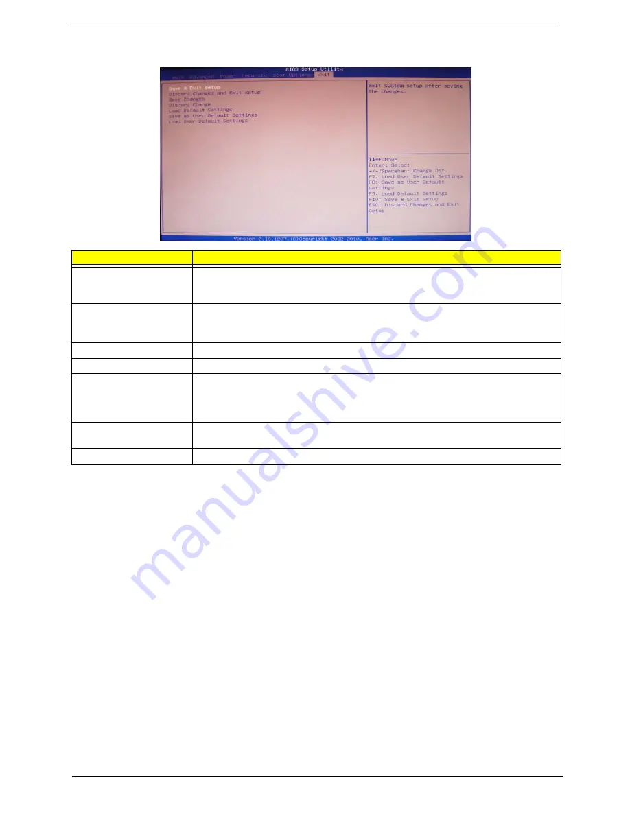
Exit
Parameter
Description
Save & Exit Setup
When you have completed the system configuration changes, select this option to leave the
BIOS Setup Utility and reboot the computer, so the new system configuration parameters can
take effect. Select
Save & Exit Setup
from the Exit menu and press
Enter
.
Discard Changes and Exit
Setup
Select this option to quit the BIOS Setup Utility without making any permanent changes to the
system configuration, and reboot the computer. Select
Discard Changes and Exit Setup
from the Exit menu and press
Enter
.
Save Changes
Select this option and press
Enter
to save all the changes and return to the BIOS Setup Utility.
Discard Changes
Use this item enables you to discard any changes that you have made.
Load Default Settings
To set this feature, select
Load Default Settings
from the Exit menu and press Enter. Then,
select OK to allow the BIOS to automatically load optimal defaults to the BIOS settings. The
Optimal settings are designed for maximum system performance, but may not work best for all
computer applications.
Save as User Default
Settings
Select this option and press
Enter
to save changes that you have made as user defaults.
Load User Default Settings
Select this option and press
Enter
to restore user defaults.
Summary of Contents for Veriton M4610
Page 1: ...Acer Veriton M4610 M4610G M4618G Service Guide PRINTED IN TAIWAN ...
Page 14: ...6 Chapter 1 Block Diagram ...
Page 69: ...Chapter 3 61 Install the I O Shielding 1 Install I O shielding into chassis ...
Page 71: ...Chapter 3 63 4 Connect the ATX 24Pin Power cable and ATX 4Pin Power cable to main board ...
Page 72: ...64 Chapter 3 Install the System FAN 1 Tie system fan cable 2 Push the system fan to chassis ...
Page 73: ...Chapter 3 65 3 Fix the four screws 4 Connect the system fan power cable to Main board ...
Page 78: ...70 Chapter 3 5 Close the lock handle IMPORTANT Install the 3 5 Card rule ...
Page 84: ...76 Chapter 3 Install the Right Side Panel 1 Install the side Panel then fix two Screws ...
Page 85: ...Chapter 3 77 Install the VGA Card 1 Remove the PCI fixer 2 Remove the PCI slot ...
Page 86: ...78 Chapter 3 3 Open the VGA card latch then press down the VGA card 4 Close the PCI fixer ...
Page 96: ...Chapter 5 88 M B Placement Jumper and Connector Information Chapter 5 ...


