background image

14

Chapter 1

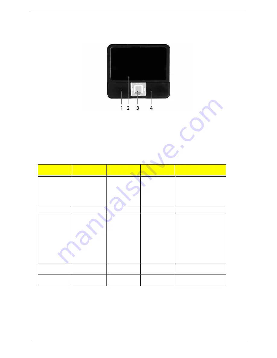
Touchpad Basics

The following teaches you how to use the touchpad:

q

Move your finger across the touchpad (2) to move the cursor. 

q

Press the left (1) and right (4) buttons located beneath the touchpad to perform selection and 
execution functions. These two buttons are similar to the left and right buttons on a mouse. 
Tapping on the touchpad is the same as clicking the left button.

q

Use the 4-way scroll (3) button to scroll up or down and move left or right a page. This button 
mimics your cursor pressing on the right scroll bar of Windows applications.

NOTE:

When using the touchpad, keep it - and your infers - dry and clean. The touchpad is sensitive to finger 

movements; hence, the lighter the touch, the better the response. Tapping too hard will not increase the 
touchpad’s responsiveness.

Function

Left Button (1)

Right Button 

(4)

Main touchpad 

(2)

Center button (3)

Execute

Click twice 
quickly

Tap twice (at 
the same speed 
as double-
clicking the 
mouse button)

Select

Click once

Tap once

Drag

Click and hold, 
then use finger 
on the touchpad 
to drag the 
cursor.

Tap twice (at 
the same speed 
as double-
clicking a 
mouse button); 
rest your finger 
on the touchpad 
on the second 
tap and drag 
the cursor.

Access context 
menu

Click once

Scroll

Click and hold to move 
up/down/left/right.

Summary of Contents for TravelMate 6592G Series

Page 1: ...TravelMate 6592 6592G Service Guide PRINTED IN TAIWAN Service guide files and updates are available on the ACER CSD web for more information please refer to http csd acer com tw...

Page 2: ...2 Revision History Please refer to the table below for the updates made on TravelMate 6592 6592G service guide Date Chapter Updates...

Page 3: ...ct to the contents hereof and specifically disclaims any warranties of merchantability or fitness for any particular purpose Any Acer Incorporated software described in this manual is sold or licensed...

Page 4: ...bits and pieces of additional information related to the current topic WARNING Alerts you to any damage that might result from doing or not doing specific actions CAUTION Gives precautionary measures...

Page 5: ...NOT be covered in this generic service guide In such cases please contact your regional offices or the responsible personnel channel to provide you with further technical details 2 Please note WHEN OR...

Page 6: ...6...

Page 7: ...erformance Management 22 Acer eRecovery Management 23 Acer eSettings Management 24 Acer ePower Management 25 Acer OrbiCam 28 Using the System Utilities 33 Acer GridVista dual display compatible 33 Lau...

Page 8: ...g the LCD Panel 81 Replacing the LCM Bezel 83 Main Module Reassembly Procedure 84 Replacing the CPU 84 Replacing the Heatsink and Fan Module 84 Replacing the I O Board 85 Replacing the Mainboard 86 Re...

Page 9: ...ymptom to FRU Error Message 110 Intermittent Problems 113 Undetermined Problems 114 Chapter 5 Jumper and Connector Locations 115 Top View 115 Bottom View 116 Connector Descriptions 117 Chapter 6 FRU F...

Page 10: ...4...

Page 11: ...20 1 WSXGA high brightness Acer CrystalBriteTM TFT LCD 1680 x 1050 pixel resolution 6 lamps q 19 WXGA high brightness Acer CrystalBriteTM TFT LCD 1440 x 900 pixel resolution 4 lamps q 16 ms typical of...

Page 12: ...cer 3DSonic 1 5W stereo speakers and one Acer BasSonic Subwoofer q Dolby Digital Live and DTS Neo PC support q Intel High Definition audio support q S PDIF Sony Philips Digital Interface support for d...

Page 13: ...ng Acer SignalUpTM wireless technology I O Ports q CRT port Suport CRT monitor q 3 USB 2 0 1 1 ports q Head Phone port q MIC In q Line In q RJ11 RJ45 q DC Jack q IR q CardBus slot q Smart Card slot q...

Page 14: ...4 Chapter 1 System Block Diagram...

Page 15: ...13 CPU Socket 7 U6 Video Memory 26 CN28 SATA HDD Connector 8 CN5 I O Board to Main Board Connector 27 CN24 BIOS Flash Memory 9 U7 Video Memory 28 U515 Audio Codec 10 CN8 DVI D Port 29 CN20 Mini PCI So...

Page 16: ...nector Touchpad to main board 2 CN502 Launch Board Connector 10 CN4001 6 pin Touchpad Board Connector 3 U503 Video Memory 11 CN504 Audio Board Connector 4 U502 Video Memory 12 CN506 DDR2 SDRAM IC 5 CN...

Page 17: ...output 3 Media volume buttons For use with Acer Arcade and other mdeia playing programs 4 8 Microphone Internal microphone for sound recording 5 Touchpad Touch sensitive pointing device which function...

Page 18: ...line in devices e g audio CD player stereo walkman 4 Microphone in jack Accepts input from external microphones 5 Headphones speaker line out jack with S PDIF support Connects to audio line out devic...

Page 19: ...ng on model 4 Optical disk access indicator Lights up when the optical drive is active 5 Optical drive eject button Ejects the optical disk from the drive 6 Emergency eject hole Ejects the optical dri...

Page 20: ...e either USB 2 0 or a single lane PCI Express technology that provides 500 Mbytes sec total throughput Formerly code named NEWCARD ExpressCards are 5 mm thick like Type II PC Cards but do not use the...

Page 21: ...device e g external monitor LCD projector 8 DVI D port Supports digital video connections 9 Ethernet RJ 45 Connects to an Ethernet 10 100 1000 based network for selected models 10 Parallel port Connec...

Page 22: ...release latch Releases the battery for removal 5 Battery bay Houses the computer s battery pack 6 Hard disk bay Houses the computer s hard disk secured with screws 7 Sub woofer Emits low frequency so...

Page 23: ...mail and Web browser buttons are pre set to email and Internet programs but can be reset by users To set the Web browser mail and programmable buttons run the Acer Launch Manager Battery Lights up wh...

Page 24: ...bar of Windows applications NOTE When using the touchpad keep it and your infers dry and clean The touchpad is sensitive to finger movements hence the lighter the touch the better the response Tapping...

Page 25: ...habetic characters typed are in uppercase Num lock Fn F11 When Num Lock is on the embedded keypad is in numeric mode The keys function as a calculator complete with the arithmetic operators and Use th...

Page 26: ...rovide a variety of function Tab Activates next taskbar button E Opens the My Computer window F1 Opens Help and Support F Opens the Find All Files dialog box R Opens the Run dialog box M Minimizes all...

Page 27: ...he display screen external monitor if connected and both Fn F6 Screen blank Turns the display screen backlight off to save power Press any key to return Fn F7 Touchpad toggle Turns the internal touchp...

Page 28: ...d software do not support the Euro symbol Please refer to www microsoft com typography faq faq12 htm for more information The US dollar sign 1 Open a text editor or word processor 2 Either directly pr...

Page 29: ...ment backs up recovers data flexibly reliably and completely q Acer eSettings Management accesses system information and adjusts settings easily q Acer ePower Management extends battery power via vers...

Page 30: ...cna decrypt any file on your system the file specific password will be used to encrypt files by default or you cna choose to enter your own file specific password when encrypting a file NOTE The passw...

Page 31: ...Optical drive deivces includes any kind of CD ROM or DVD ROM drives q Floppy disk drives 3 5 inch disks only To activate Acer eLock Management a password must be set first Once set you may apply lock...

Page 32: ...performance of your Acer notebook It provides you with the following options to enhance overall system performance q Memory optimization releases unused memory and check usage q Disk optimization rem...

Page 33: ...dden partition on your system s HDD User created backups are stored on D drive Acer eRecovery Management provides you with q Password protection q Recovery of applications and drivers q Image data bac...

Page 34: ...Acer eSettings Management allows you to inspect hardware specifications and to monitor the system health status Furthermore Acer eSettings Management enables you to optimize your Windows operating sys...

Page 35: ...AN Bluetooth CardBus Memory Card Audio and Wired LAN DC Mode To suit your usage there are four pre defined profiles Entertainment Presentation Word Processing and Maximum Battery Or you can define up...

Page 36: ...ced Settings to q Set alarms q Re load factory defaults q Select what actions will be taken when the cover is closed and set passwords for accessing the system after Hibernation or Standby q View info...

Page 37: ...Chapter 1 27 Acer ePresentation Management Acer ePresentation Management lets you select from two of the most common projector resolutions XGA and SVGA...

Page 38: ...your Acer OrbiCam Rotating the Acer Orbicam The Acer OrbiCam rotates 225 degrees counterclockwise to achieve the desired angle Refer to the illustrations below For your convenience the camera snaps 45...

Page 39: ...Click Options to display the Window Preview and Folder tabs Use the options to change the capture window size preview settings and the folder for captured photos or videos Camera Settings q Basic set...

Page 40: ...video clip NOTE By default all photos and videos are saved in the My Pictures and My Videos folder Using the Acer OrbiCam as webcam The Acer OrbiCam is automatically selected as the capture device of...

Page 41: ...he left icon down arrow button then select Single User or Multiple Users from the pop up menu For multiple users the face tracking feature automatically centers all the users face in the capture windo...

Page 42: ...ideo effects The Video Effect Selection window appears as below 2 Click on a video effect to use The selected effect appears in the video effects section of the VisageON window NOTE When using avatars...

Page 43: ...idVista is a handy utility that offers four pre defined display settings so you can view multiple windows on the same screen To access this function please go to Start All Programs and click on Acer G...

Page 44: ...ond monitor is set to the manufacturer s recommended value Launch Manager Launch Manager allows you to set the four easy launch buttons located above the keyboard You can access the Launch Manager by...

Page 45: ...35W Ambient 35 degree C CPU Temperature Fan Speed Acoustic Level Core 0 Core 1 rpm dBA 86 86 3700 39 88 88 3450 36 5 91 91 3150 34 5 95 95 2800 31 BIOS Item Specification BIOS vendor Pheonix BIOS Vers...

Page 46: ...d 0 9V Supports DIMM package 200 pin soDIMM Memory module combinations You can install memory modules in any combinations as long as they match the above specifications Memory Combinations Slot 1 Slot...

Page 47: ...set Built in ICH6 M Data throughput 11 54 Mbps Protocol 802 11b g Interface Mini PCI type II Hard Disk Drive Interface Item Vendor Model Name Seagate 40G ST9402112A Toshiba MK4025GAS Hitachi HTS421240...

Page 48: ...uffer Memory 2MB Interface Enhanced IDE ATAPI compatible Applicable disc format DVD DVD ROM DVD 5 DVD 9 DVD 10 DVD 18 DVD R read single border DVD RW DVD RAM 2 6GB 4 7GB CD CD DA CD ROM CD ROM XA CD R...

Page 49: ...cy Release Power Requirement Input Voltage 5 V 5 Operating Audio Interface Item Specification Audio Controller ALC655 Audio onboard or optional Built in Mono or Stereo Stereo Resolution 16 bit stereo...

Page 50: ...location Left panel Supports ZV Zoomed Video port No ZV support Supports 32 bit CardBus Yes System Board Major Chips Item Controller Core logic Intel 910GML ICH6 M VGA Built in Intel 910GML LAN RealTe...

Page 51: ...14 1 inches 14 1 inches 14 1 inches 14 1 inches Active Area mm 304 1x228 1 304 1x228 1 304 1x228 1 Display resolution pixels 1024x768 XGA 1024x768 XGA 1024x768 XGA Pixel Pitch 0 297x0 297 0 099x0 297...

Page 52: ...to 63Hz Maximum input AC current 1 7A Inrush current 220A 115VAC 220A 230VAC Efficiency 82 min 115VAC input full load System Power Management ACPI mode Power Management Mech Off G3 All devices in the...

Page 53: ...hout entering BIOS Setup Utility please set the parameter to enabled Press F12 during POST to enter multi boot menu In this menu user can change boot device without entering BIOS SETUP Utility Informa...

Page 54: ...em q Press while you are in any of the menu options to go to the Exit menu q In any menu you can load default settings by pressing t You can also press u to save any changes made and exit the BIOS Set...

Page 55: ...tem BIOS version VGA BIOS Ver This field displays the VGA firmware version of the system Serial Number This field displays the serial number of this unit Asset Tag Number This field displays the asset...

Page 56: ...for reference only Actual values may differ KLIJ Move Enter Select PU PD Value F10 Save and Exit ESC Exit F1 General Help F5 Previous Values F7 Optimized Defaults Network Boot Enabled F12 Boot Menu Di...

Page 57: ...B Video Memory Shows the VGA memory size Quiet Boot Determines if Customer Logo will be displayed or not shows Summary Screen is disabled or enabled Enabled Customer Logo is displayed and Summary Scre...

Page 58: ...the parallel port if enabled ECP SPP EPP ASF Configuration q Minimum Watchdog Timeout q BIOS Boot Timeout q OS Boot Timeout q Power on wait Time Access the ASF Submenu for the following features q Mi...

Page 59: ...d Exit ESC Exit F1 General Help F5 Previous Values F7 Optimized Defaults Password on Boot Disabled Current TPM State Change TPM State No Change Set HDD Password Enter Set Supervisor Password Enter Set...

Page 60: ...ssword Clear or Set Set Supervisor Password Press Enter to set the supervisor password When set this password protects the BIOS Setup Utility from unauthorized access The user can not either enter the...

Page 61: ...firm New Password field IMPORTANT Be careful when typing the password as the characters do not appear on the screen 3 Press Enter After setting the password the computer sets the Supervisor Password I...

Page 62: ...ting the password the computer sets the Supervisor Password Is parameter to Set 5 If desired you can enable the Password on Boot parameter 6 When you are done save the changes and exit the BIOS Setup...

Page 63: ...Chapter 2 53...

Page 64: ...ct a device then press F6 to move it up the List or F5 to move it down the list Press Esc to escape the menu KLIJ Move Enter Select PU PD Value F10 Save and Exit ESC Exit F1 General Help F5 Previous V...

Page 65: ...t utility without saving setup data to CMOS Load Setup Defaults Load default values for all SETUP item Discard Changes Load previous values from CMOS for all SETUP items Save Changes Save Setup Data t...

Page 66: ...ry Diskette before you use the Phlash utility NOTE Do not install memory related drivers XMS EMS DPMI when you use the Phlash NOTE Please use the AC adaptor power supply when you run the Phlash utilit...

Page 67: ...preventing electrostatic discharge q Small Philips screw driver q Philips screwdriver q Plastic flat head screw driver q Tweezers NOTE The screws for the different components vary in size During the...

Page 68: ...n Before You Begin Before proceeding with the disassembly procedure make sure that you do the following 1 Turn off the power to the system and all peripherals 2 Unplug the AC adapter and all power and...

Page 69: ...entation on the entire disassembly sequence and instructs you on the components that need to be removed during servicing For example if you want to remove the system board you must first remove the ke...

Page 70: ...60 Chapter 3 LCM Module Disassembly Flowchart...

Page 71: ...the computer over Release the battery lock as shown 2 Push the release latch the battery pops up 3 Remove the battery Removing the Cover Securing Screws and Covers 1 Locate and loosen the seventeen 17...

Page 72: ...62 Chapter 3 2 Locate and remove the memory and HDD cover screws as shown 3 Remove the memory cover as shown 4 Remove the HDD cover as shown Removing the HDD 1 Locate the plastic tab on the HDD...

Page 73: ...l tag 3 Pull away from the connector and upward as shown to remove the HDD from the chassis Removing the Memory Module 1 Push the two release levers on the memory module outward as shown NOTE The memo...

Page 74: ...ide of the memory bay 2 Using fine tweezers grip the white taped wire and pull upward until it is released from the board 3 Repeat for the red taped and no tape wires 4 Remove cables to access Wireles...

Page 75: ...Chapter 3 65 Removing the ODD 1 Push and hold the ODD latch as shown 2 Remove ODD Removing Dummy Trays 1 Locate Dummy Tray 1 and press the cover inwards as shown 2 Remove Dummy Tray 1...

Page 76: ...g tools to remove the Switch Cover may cause damage to the outer casing It is recommended that only fingers are used to remove the Switch Cover 1 Turn the computer over Locate and remove the two secur...

Page 77: ...nds remove the Switch Cover from the chassis Removing the Keyboard 1 Locate and remove the two screws as shown 2 Using both hands lift the top edge of the keyboard as shown 3 Turn the keyboard over as...

Page 78: ...g fine tweezers release the first cable lock as shown and remove the cable from the socket 5 Using fine tweezers release the second cable lock as shown and remove the cable from the socket 6 Remove ke...

Page 79: ...releasing the locking latch and removing the cable as shown 2 Disconnect the second cable by releasing the locking latch and removing the cable as shown NOTE Move the cable away from the work area to...

Page 80: ...apter 3 Removing the Switch Board 1 Locate and remove the two screws as shown 2 Remove the Switch Board from the chassis Removing the Modem Module 1 Disconnect the two cables from the Modem Module as...

Page 81: ...g screws as shown 3 Lift the Modem Module clear of the chassis Removing the Antenna Cables 1 Remove the Antenna Cables from the securing pins as shown 2 Pull the three Antenna Cables from the undersid...

Page 82: ...amage 1 Disconnect the LCM Module cable as shown 2 Locate and remove the four screws as shown 3 Lift the LCM Module upward to remove from the chassis Removing the TouchPad 1 Lift the rear edge of the...

Page 83: ...er 3 73 Removing the Mainboard 1 Locate the three connectors yellow markers as shown 2 Disconnect the connectors using tweezers as shown 3 Locate and remove the two screws as shown to release the Main...

Page 84: ...while removing the mainboard ease the computer case outward to clear the obstruction 5 Lift the mainboard clear of the chassis Removing the I O Board 1 Locate and remove the two screws as shown 2 Lif...

Page 85: ...d over Locate and remove the five screws red markers and fan connector yellow marker from the mainboard 2 Remove the Heatsink securing bracket as shown 3 Remove the Heatsink as shown 4 Steady the Main...

Page 86: ...76 Chapter 3 Removing the CPU 1 Using a screw driver unscrew the CPU counter clockwise 2 Remove the CPU from the bracket as shown...

Page 87: ...ing 1 Locate and remove the four mylar small red markers and two rubber large red markers screw covers as shown NOTE Do not discard the screw covers they are reusable 2 Remove the six bezel securing s...

Page 88: ...78 Chapter 3 5 Remove the bezel from the LCM Module Removing the LCD Panel 1 Locate and remove the six screws as shown 2 Locate the three panel connectors as shown Disconnect the cables as shown...

Page 89: ...e WebCam Module and remove the LCD panel by lifting the hinge as shown 4 Locate and remove the Inverter Board screw as shown 5 Grip the Inverter Board and lift upward to remove 6 Grip the WebCam Modul...

Page 90: ...etach the adhesive pads 8 Hold the printed circuit board with one hand and disconnect the cable by pulling away from the connector 9 Locate and remove the four screws two on each side securing the LCD...

Page 91: ...n the LCD brackets the four screw holes two on each side on the LCD Panel as shown 2 Secure the LCD brackets to the LCD panel 3 Insert the cable into the cable connector on the LCD Panel as shown 4 Al...

Page 92: ...5 Place the WebCam Module in the mounting as shown 6 Place the Inverter Board in the mounting and secure with the screw provided 7 Place the LCD Panel in the mounting and secure the three panel connec...

Page 93: ...ovided Replacing the LCM Bezel 1 Locate the bezel correctly and press down the edges until there are no gaps between the bezel and the LCM Module 2 Secure the six screws provided and replace the mylar...

Page 94: ...he CPU 1 Insert the CPU into the CPU bracket as shown 2 Using a screw driver tighten the screw clockwise as shown to secure the CPU in place Replacing the Heatsink and Fan Module 1 Place the Fan Modul...

Page 95: ...3 85 3 Align the Heatsink Securing Bracket as shown 4 Secure the five screws and fan connector as shown Replacing the I O Board 1 Insert the board rear edge first as shown 2 Replace the two screws as...

Page 96: ...chassis rear edge first and press down to install Replace the two securing screws as shown NOTE If any resistance is met while installing the mainboard ease the computer case outward to clear the obst...

Page 97: ...and that all cables pass through the casing properly Replacing the LCM Module 1 Align the four screw holes on the LCM Module hinges with the corresponding screw holes on the chassis Lower the LCM Modu...

Page 98: ...from the underside of the computer Place the three cables in the wiring conduit and secure in place using the cable pins on the chassis 2 Connect the LCM Module cable to the connector on the chassis a...

Page 99: ...t the Modem cables as shown Replacing the Switch Board 1 Place the Switch Board in the mounting as shown 2 Secure the Switch Board in place using the screw provided Reconnecting the TouchPad 1 Replace...

Page 100: ...t the second cable as shown and lock the latch to secure the cable in place Replacing the Keyboard 1 Using fine tweezers insert the thicker cable into the socket and secure the locking latch as shown...

Page 101: ...e Keyboard into place toward the TouchPad and secure using the two screws provided 5 Turn the Computer over and insert the screw as shown Replacing the Switch Cover 1 Turn the computer over Place the...

Page 102: ...Replacing the Dummy Trays 1 Insert Dummy Tray 2 and push into the slot until flush with the chassis cover 2 Insert Dummy Tray 1 and push into the slot until flush with the chassis cover Replacing the...

Page 103: ...push into the connector NOTE The card remains at an angle until the screws are inserted 2 Secure the card in position using the two screws provided 3 Reconnect the three Antenna Cables as shown pushi...

Page 104: ...ory module into the socket and press downward until it clicks into place Replacing the HDD 1 Place the HDD in the mounting rear edge first as shown 2 Push firmly toward the connector to secure the HDD...

Page 105: ...95 2 Replace the two screws to secure the cover in place 3 Replace the memory cover as shown 4 Replace the two screws to secure the cover in place 5 Replace the seventeen 17 screws to secure the cover...

Page 106: ...96 Chapter 3 Replacing the Battery Pack 1 Place the battery in the cradle rear edge first as shown 2 Push the battery downward until it clicks in to place 3 Engage the battery lock as shown...

Page 107: ...h page to go to Symptoms Verified Go To Power failure The power indicator does not go on or stay on Power System Check on page 99 POST does not complete No beep or error codes are indicated Power On S...

Page 108: ...abel can cause damage to the drive or can cause the drive to fail Do the following to select the test device 1 Boot from the diagnostics diskette and start the diagnostics program 2 See if CD ROM Test...

Page 109: ...in the message window NOTE Make sure that the DIMM is fully installed into the connector A loose connection can cause an error Power System Check To verify the symptom of the problem power on the com...

Page 110: ...following q Replace the System board q If the problem is not corrected see Undetermined Problems on page 114 q If the voltage is not correct go to the next step NOTE An audible noise from the power a...

Page 111: ...battery pack that has less than 50 of the total power remaining when installed in the computer If the battery status indicator does not light up remove the battery pack and let it return to room tempe...

Page 112: ...xt possible FRU to be replaced when servicing a computer If the symptom is not listed see Undetermined Problems on page 114 The following lists the error messages that the BIOS displays on the screen...

Page 113: ...ult Settings in BIOS Setup Utility Hard disk drive System board Stuck Key see Keyboard or Auxiliary Input Device Check on page 98 Keyboard error see Keyboard or Auxiliary Input Device Check on page 98...

Page 114: ...Setup Utility System cache error Cache disabled System board CPU ID System board DMA Test Failed DIMM System board Software NMI Failed DIMM System board Fail Safe Timer NMI Failed DIMM System board D...

Page 115: ...source battery pack and power adapter See Power System Check on page 99 Reconnect the LCD connector Hard disk drive LCD inverter ID LCD cable LCD Inverter LCD System board No beep power on indicator t...

Page 116: ...efore memory autosize 18h 8254 timer initialization 1Ah 8237 DMA controller initialization 1Ch Reset Programmable Interrupt Controller 20h 1 3 1 1 Test DRAM refresh 22h 1 3 1 3 Test 8742 Keyboard Cont...

Page 117: ...Enable external and CPU caches 69h Setup System Management Mode SMM area 6Ah Display external L2 cache size 6Bh Load custom defaults optional 6Ch Display shadow area message 6Eh Display possible high...

Page 118: ...key lock A4h Initialize Typematic rate A8h Erase F2 prompt AAh Scan for F2 key stroke ACh Enter SETUP AEh Clear Boot flag B0h Check for errors B2h POST done prepare to boot operating system B4h 1 One...

Page 119: ...uge Segment E9h Initialize Multi Processor EAh Initialize OEM special code EBh Initialize PIC and DMA ECh Initialize Memory type EDh Initialize Memory size EEh Shadow Boot Block EFh System memory test...

Page 120: ...displayed LCD inverter ID LCD inverter LCD cable LCD System board Indicator Related Symptoms Symptom Error Action in Sequence Indicator incorrectly remains off or on but system runs correctly Reconne...

Page 121: ...o sound Speaker System board Power Management Related Symptoms Symptom Error Action in Sequence The system will not enter hibernation See Save to Disk S4 on page 42 Keyboard if control is from the key...

Page 122: ...5 LCD CRT Both display switching System board USB does not work correctly System board Print problems Ensure the Parallel Port in the Onboard Devices Configuration of BIOS Setup Utility is set to Enab...

Page 123: ...discharge or software errors FRU replacement should be considered only when a recurring problem exists When analyzing an intermittent problem do the following 1 Run the advanced diagnostic test for t...

Page 124: ...perating correctly See Power System Check on page 99 1 Power off the computer 2 Visually check them for damage If any problems are found replace the FRU 3 Remove or disconnect all of the following dev...

Page 125: ...TR 5 CN4 Key board FFC CNTR 6 CN6 Fine track FFC CNTR 7 CN7 Smart card FFC CNTR 8 CN8 Touch pad FFC CNTR 9 CN9 MIC cable CNTR 10 CN12 3G card CNTR 11 CN14 Blue tooth cable CNTR 12 CN11 Speaker cable C...

Page 126: ...t 5 CN1002 VGA port 19 CN1009 CPU socket 6 JACK1000 DC IN jack 20 CN1014 USB 7 CN1000 FAN cable CNTR 21 CN1010 USB 8 CN1005 Docking CNTR 22 CN1007 1394 9 CN1018 Second battery CNTR 23 U6002 North brid...

Page 127: ...DOCK I O PIN No Signal name I O PIN No Signal name I O 1 V5S 21 LVDS_TXDL2 I 2 INV_PWM_3 I 22 GND 3 V5S 23 LVDS_TXDL2 I 4 GND 24 LVDS_TXDL1 I 5 BKLTEN I 25 GND 6 LVDS_TXCU I 26 LVDS_TXDL1 I 7 GND 27 L...

Page 128: ...118 Chapter 5...

Page 129: ...ge is made it will not be noted on the printed Service Guide For ACER AUTHORIZED SERVICE PROVIDERS your Acer office may have a DIFFERENT part number code from those given in the FRU list of this print...

Page 130: ...120 Chapter 6 TravelMate 6592 6592G Exploded Diagram 1 2 3 4 5 6 7 8 9 10 11 12...

Page 131: ...135DB BBJF LF AP 13501 004 ADAPTER 135W 19V 3PIN LITE ON PA 131 08 RI LF AP 13503 006 ADAPTER 135W 3PIN LSE SLS0317A19A52LF LF AP 13506 002 BATTERY BATTERY PACK SANYO LI ION 8 CELL2 4 4800MAH BT 0080...

Page 132: ...11 A B G ROW INTEL MM874511 KI GLN01 003 MINI WIRELESS BOARD 802 11 A B G JP INTEL MM874740 KI GLN01 004 MINI WIRELESS LAN BOARD 802 11BG INTEL WM3945AGBG KI GLN01 005 BLUETOOTH BOARD FOXCONN T60H928...

Page 133: ...OWER CORD 3PIN UK 27 AAMVN 004 POWER CORD 3PIN CHINA 27 AAMVN 005 POWER CORD 3PIN SWISS 27 AAMVN 006 POWER CORD SOUTH AFRICA AIL 27 AAMVN 007 POWER CORD 3PIN SOUTH AFRICA 27 AAMVN 008 POERR CORD 3PIN...

Page 134: ...LE 6 PINS 50 AAMVN 006 BUTTON BOARD CABLE 12 PINS 50 AAMVN 007 MODEM CABLE WITH RJ11 CONNECTOR 50 AAMVN 010 CASE COVER BRACKET ASSEMBLY LOWER CASE 60 AAMVN 001 UPPER CASE 60 AAMVN 002 MIDDLE COVER 60...

Page 135: ...Y THERMAL COVER 60 AAMVN 004 SUPPORT COVER 60 AAMVN 005 HDD COVER 42 AAMVN 001 TOUCHPAD FRAME 42 AAMVN 002 MINI DUMMY CARD 42 AAMVN 003 PCMCIA DUMMY CARD 42 AAMVN 004 Category No Part Name and Descrip...

Page 136: ...23001 DTP CPU INTEL YONAH CORE DUO FSB 667 1 66G 2M SL9DM NO VT KC 23E01 DTP CPU INTEL YONAH CORE DUO FSB 667 1 83G 2M SL8VQ KC 24001 DTP CPU INTEL YONAH CORE DUO FSB 667 2 0G 2M SL8VP KC 25001 DTP C...

Page 137: ...MULTI TOSHIBA TS L632D W O BEZEL KU 00801 014 DVD RW DRIVE 8X S MUTI PANASONIC UJ 850 W O BEZEL KU 00807 025 DVD RW MODULE SUPER MULTI SLOT IN PIONEER GBASE W BEZEL 6M AAMVN 004 OPTICAL BRACKET 33 AAM...

Page 138: ...S F W A60A KH 10007 004 HDD 100G 5400RPM SAMSUNG HM100JC KH 1000B 002 HDD 120G 5400RPM SEAGATE ST9120821A LF MERCURY 2 FW 3 06 KH 12001 024 HDD 120GB TOSHIBA 2 5 IN 5400RPM MK1234GAX LF TAURUS FW AC00...

Page 139: ...KH 1000B 003 HDD 120G SEAGATE 5 4K SATA ST9120821AS LF MERCURY 2 FW 3 06 KH 12001 025 HDD 120G TOSHIBA 5 4K SATAI1 5G W NCQ MK1234GSX LF TAURUS FW AH001A KH 12004 003 HDD 120G 5400RPM SATA SAMSUNG HM...

Page 140: ...KB AAK07 016 AS9800 KEYBOARD DARFON HUNGAIAN KB AAK07 017 AS9800 KEYBOARD DARFON NORWAY KB AAK07 018 AS9800 KEYBOARD DARFON DANISH KB AAK07 019 AS9800 KEYBOARD DARFON TURKISH KB AAK07 020 AS9800 KEYBO...

Page 141: ...GO 60 AAMVN 007 LCD BARCKET L W HINGE 19 1IN SAMSUNG 33 AAMVN 003 LCD BARCKET R W HINGE 19 1IN SAMSUNG 33 AAMVN 004 LCD 19IN WXGA SAMSUNG LTN190 M2 000 8MS 300NITS NON GLARE LK 19106 002 LCD MODULE 19...

Page 142: ...AAMVN 006 LCD COVER W LOGO 60 AAMVN 007 LCD BARCKET L W HINGE 19 1IN SAMSUNG 33 AAMVN 003 LCD BARCKET R W HINGE 19 1IN SAMSUNG 33 AAMVN 004 LCD 19IN WXGA SAMSUNG LTM190 M2 L01 G 8MS 300NITS GLARE TYPE...

Page 143: ...L W HINGE 20 1IN 33 AAMVN 007 LCD BARCKET R W HINGE 20 1IN 33 AAMVN 008 LCD 20 1IN WSXGA AUO M201EW01 V 0 8MS 300NITS NON GLARE LK 20105 002 LCD MODULE 20 1 WXGA QDI GLARE 6M AAMVN 023 INVERTER BOARD...

Page 144: ...AAK0B 003 MAINBOARD G73M 256MB SATA W O CPU W VGA HEATSINK PCMCIA SLOT RTC BATTERY MB AAK0B 004 MAINBOARD G73M 256MB SATA W O CPU W VGA HEATSINK PCMCIA SLOT RTC BATTERY MB AAK0B 004 MAINBOARD G73M 256...

Page 145: ...667 256MB NANYA NT256T64UH4A1FN 3C LF KN 25603 027 SO DIMM DDRII667 256MB INFINEON HYS64T32000HDL 3S B 09U G KN 25602 032 SO DIMM DDRII667 256MB HYNIX HYMP532S64BP6 Y5 LF 09UM KN 2560G 013 SO DIMM DDR...

Page 146: ...C MCE05 001 MCEIR 210 RECEIVER LC MCE05 002 MCEBS 220 IR BLASTER LC MCE05 003 ACCESSORY BOARD TV TUNER M103 S W MPEG HYBRID 55 AAMVN 006 TV TUNER M104 HW MPEG ANALOG 55 AAMVN 007 TV TUNER M115 ADT HYB...

Page 147: ...N 003 SCREW 86 AAMVN 004 SCREW 86 AAMVN 005 SCREW 86 AAMVN 006 SCREW 86 AAMVN 007 SCREW 86 AAMVN 008 SCREW 86 AAMVN 009 SCREW 86 AAMVN 010 SCREW 86 AAMVN 011 SCREW 86 AAMVN 012 Category No Part Name a...

Page 148: ...138 Chapter 6...

Reviews: